- Hits: 2938
Process Control System Realization
1-Process control system for the Electrolyzer
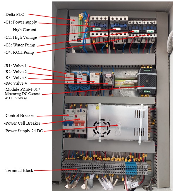
2-Control Panel
3-Control Panel - Wiring Diagram
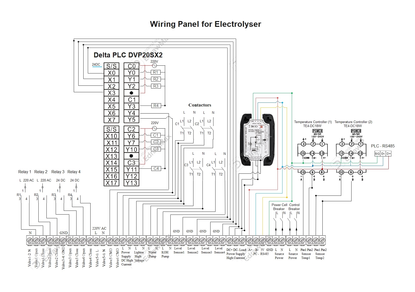 Control Panel - Wiring Diagram
4-Instruments


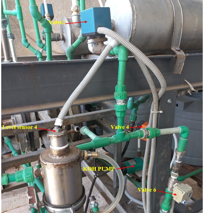
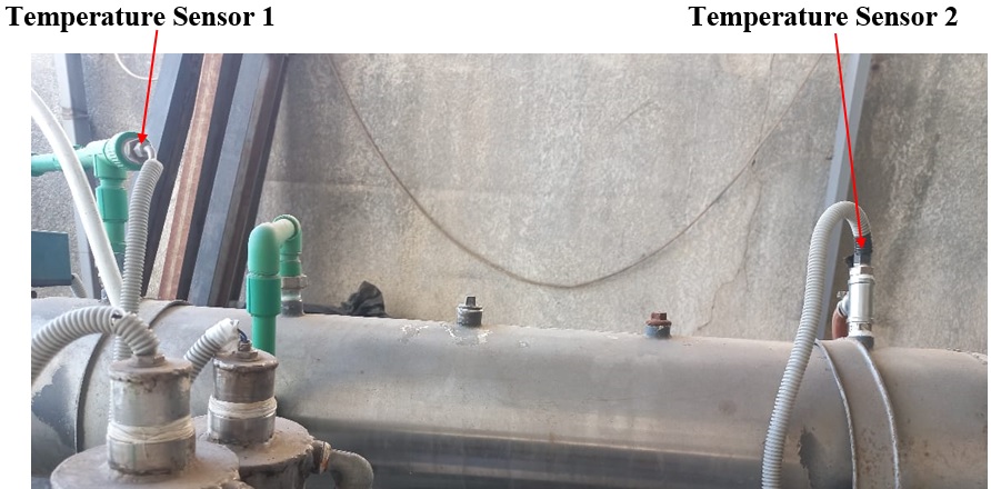
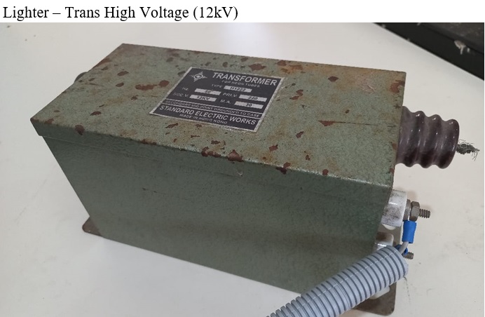
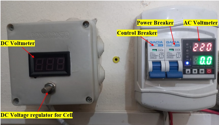
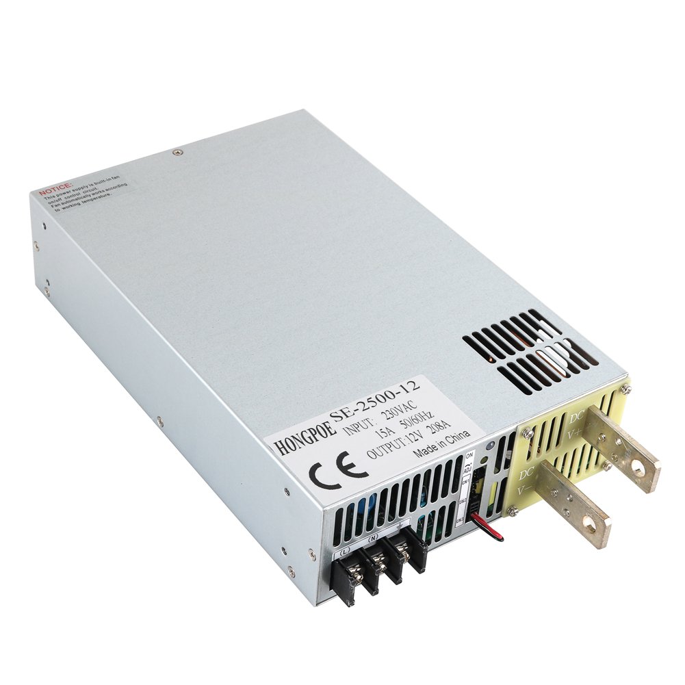
Power Supply High Current - Panel & Cable
6-Material Specification
a-Temperature Controller TE4-DC18W
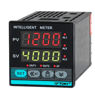
http://www.sah.rs/media/sah/techdocs/te-w_manual.pdf
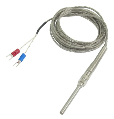
b-Temperature Sensor - K Type Thermocouple
c-Motorized Ball Valves BV03G2D15SA/220
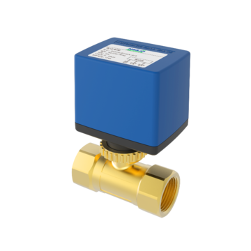
d-Motorized Ball Valves A20-T15-S2-B 1/2" DN15 SS316 CR303 AC220v
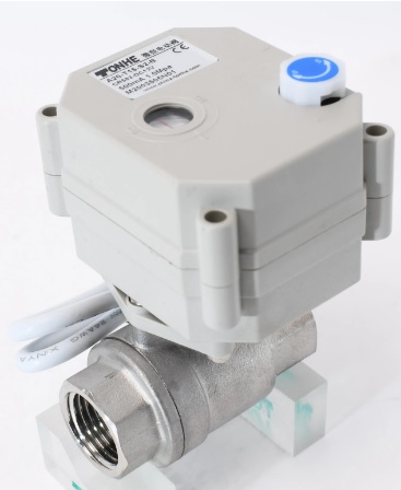
Motorized Ball Valves A20-T15-S2-B
e-Adjustable Power Supply: SE-2500-12
7-Graphical User Interface
Graphical User Interface code (C#)
8-Algorithme electrolyser
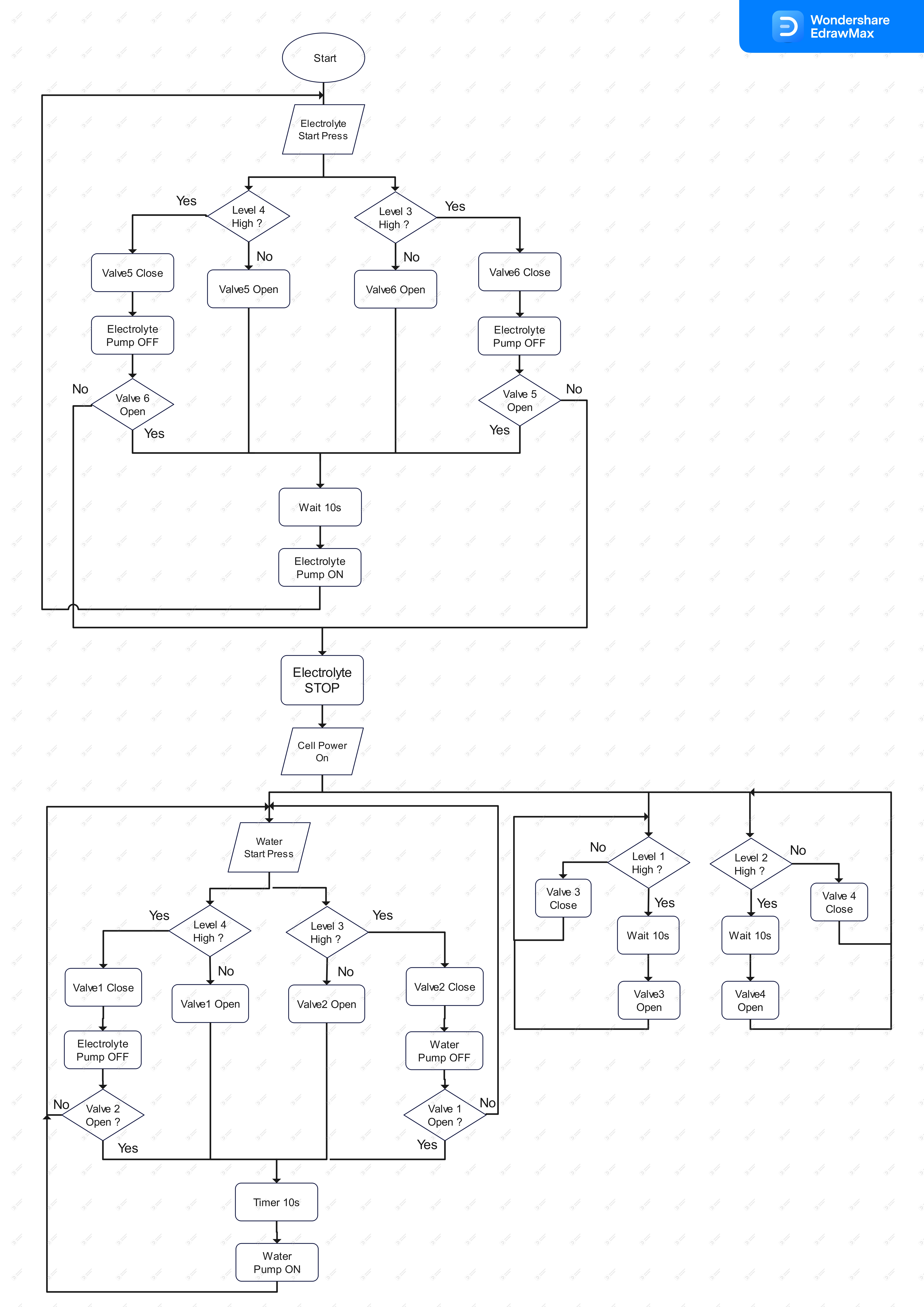
Check GUI video clip:
Check Electrolyser PCS report:
ICPT_Electrolyser_ProcessControlSystem.pdf
ICPT_Electrolyser_ProcessControlSystem.doc
Related Sites/Items:
|
System Specification |
|
|
Mechanical Design |
|
|
Process Control System Spec./Design |
|
|
Mechanical Realization |
|
|
Process Control System Realization (PLC+GUI) |
|
|
System Test Specification |
|
|
System Testing |
