- Hits: 3626
Mass spectrometry detector
System Concept, Electronics (last update: 31.8.23)
Mass spectrometer overview poster (PNG)
Mass spectrometer detector overview (pdf)

Design
Faraday's cup design and modules (pdf)
3D module of faraday's cup (FreeCad)


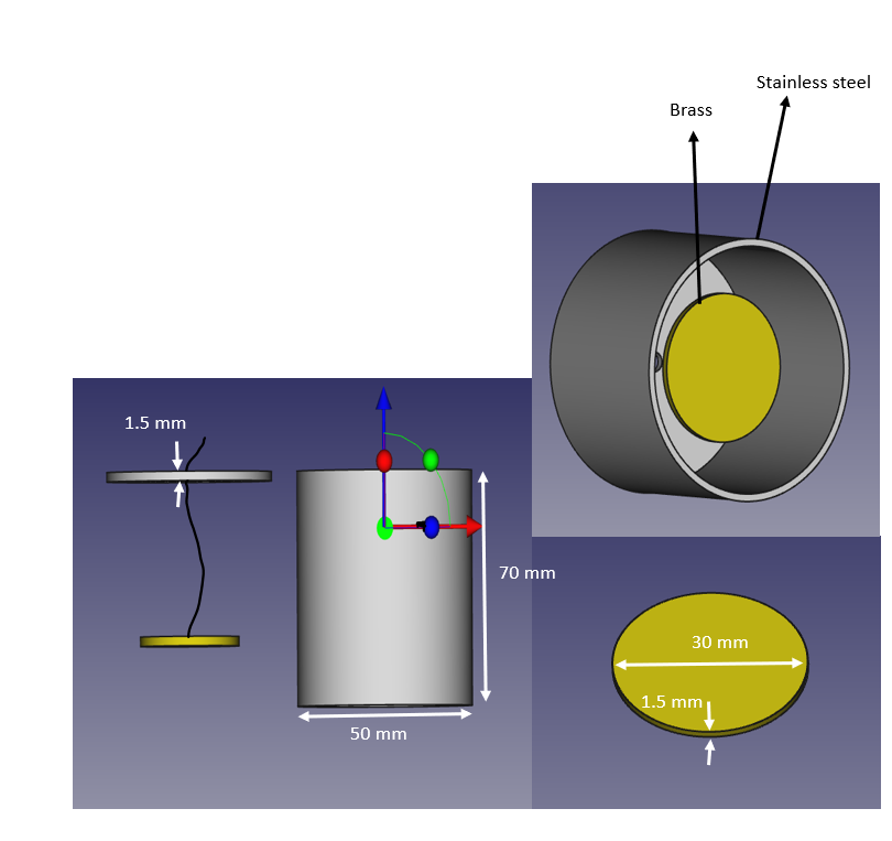
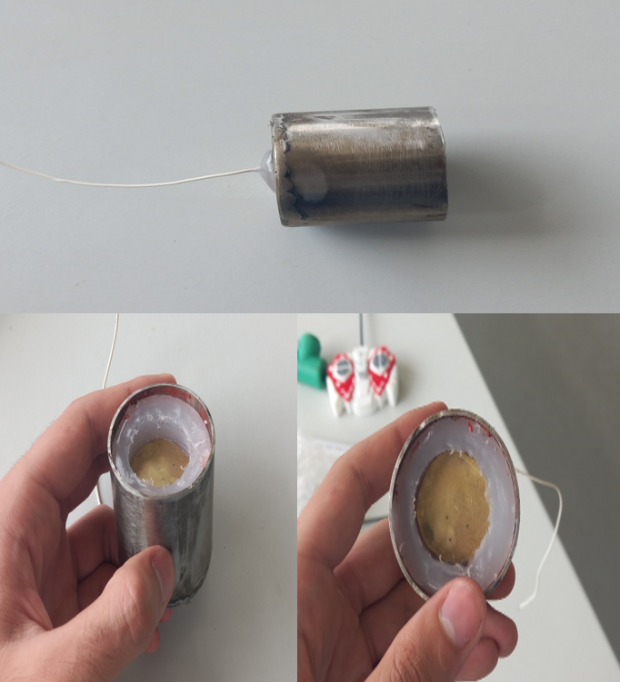
Faraday's cup (test module)

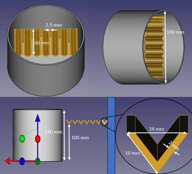
Faraday's cup final design (details in here)
Electronics and Amplification Process: (last update: 20.12.25)
https://aecenar.com/jdownloads/IAP%20Institute/21092023_Amplifier%20circuit%20of%20FC.pdf
PCB version of the amplifier circiut.
Amplifier circuit of FC module on a bread board
After the amplification process comes the ADC (Analog-Digital Converter):
As a proof of concept, a circuit was built and simulated using Proteus software.
The code was writen and compiled by Microchip Studio software using "Assembly code" (optional and can be changed).
The Arduino Uno (Atmega328PB microprocessor) only has 6 analog pin which are used for ADC tasks, which means for the time being only 6 signals will be measured.
The simulation Logic:
The analog pin on the ATmega328 (PC0 -> PC5) takes the signal voltage from variable resistors and display it on
an LCD 16x2 with the following format:
row 1: R1 - R2 - R3 - R4 - R5 - R6 - R7 (resistor number)
row 2: V1 - V2 - V3 - V4 - V5 - V6 - V7 (voltage signals)
Now the voltage signal will not be shown as values in volts, instead it will be encoded as follows:
0v -> 5v translates to 0 -->1 -->2....9 -->a -->b -->c....z -->A -->B -->C....Z
This gives us 0.08 Volts per step
Where 0 -->0v & Z -->5v
This format was chosen (for the time being) due to its simplicity and the lack of space on the LCD.
Realization of Faraday cups (last update: 14.2.24)
cutting copper for Faraday cups:


