- Hits: 1589
HM Mass Spectrometer - Basics
Poster HM Mass Spectrometer Design (pptx)
CHAPTER 1: Basics
Mass Spectrometer Principle
Mass spectrometers analyze the distinct fragments or ions produced by organic molecules by bombarding the compound with electrons to create positively charged ions. The resulting mass spectrum displays each ion as a peak. [1]
MS consists of four main parts: the ionization source where the molecules get ionized, the acceleration zone where ions gain higher velocity, the deflection determined by the mass-to-charge ratio (m/z), and finally, the detection part which is proportional to the abundance of ions (see Figure 1).

Figure 1
Ionization Source
The ionization source is a device that can be used in several methods and techniques to ionize molecules. The method chosen depends on the type of the sample, such as gas, liquid, or solid. Since our project focuses on toxic gases, electron impact ionization is the suitable method in our case. [2]
The sample should be in a gaseous phase to enter the ion source. In this situation, we use a heated filament made of tungsten to collide with the gaseous sample molecules and generate positive ions. Since it is much more difficult to remove more than one electron, most of the ions will have a charge of +1.
It is important to note that the ion source must be evacuated to prevent contact with air molecules. [3]
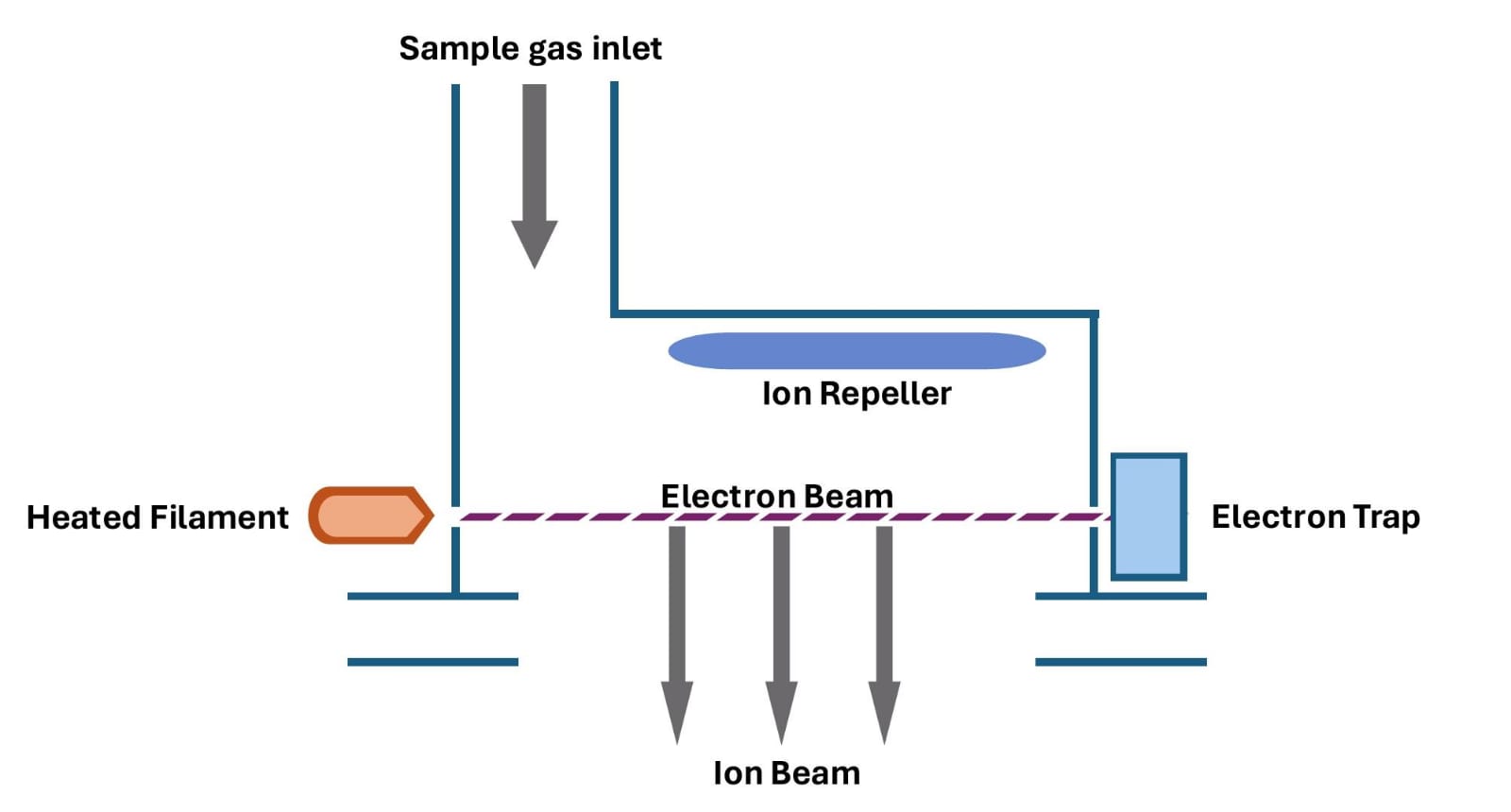
Figure 2
Acceleration Zone
The positive ions are pushed out by the ion repeller, which is a positively charged plate (see Figure 2). Subsequently, they pass through the acceleration zone, where they are subjected to an intense electric field specifically designed to accelerate them and increase their kinetic energy.
The acceleration zone is created by three plates that are gradually charged negatively, with the first disc being strongly negative (300 V), generating a powerful electric field that propels the positive ions towards the last disc.
As the ions progress towards the subsequent discs, they continue to be accelerated by the electric field until they reach the final disc, which is neutral and acts as a ground (see Figure 3).
The precise control of the electric field between the discs ensures optimal focusing of the positive ions, preventing any undesired dispersion or deflection. An intermediate disc, also negatively charged (150 V) but at a reduced intensity compared to the first disc, ensures a gradual acceleration of the positive ions. This stabilization in their trajectory allows them to pass to the third disc, which acts as a final barrier, enabling the positive ions to reach the region of the mass spectrometer dedicated to their analysis.
We should note that all positive ions will have the same kinetic energy after acceleration. [4]
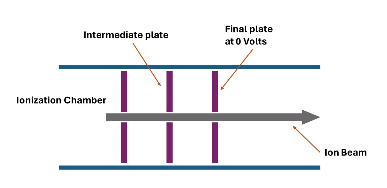
Figure 3
Deflection Zone
The deflection zone in a mass spectrometer is a crucial step for separating ions based on the mass-to-charge ratio (m/z), allowing us to identify each chemical species in our sample.
The ions emerging from the ionization source enter a region with a uniform magnetic field, causing them to experience a magnetic force that deviates them from their initial trajectory.
Ions with higher m/z ratios will experience less deflection compared to ions with lower m/z ratios. This difference enables us to separate ions based on their masses. Since most ions carry the same charge of +1, the extent of deflection will be determined by the mass of the ions. [5]
The path of the ions is typically curved with a radius R. This trajectory is governed by either Biot-Savart's law or the Lorentz force. [6]
In other words, the heavier the ions, the less they deflect. Furthermore, they will require a stronger magnetic field to deflect them. We recognize that ion stream C is heavier than B, which is heavier than A. (see Figure 4).

Figure 4
Detection of Ions
In the realm of mass spectrometry, the detection stage holds significant importance as it pertains to the identification of ions that have traversed the mass analyzer's pathway.
The detector plays an essential role in converting ions into a detectable and usable signal.
Once sorted by the mass analyzer, the ions enter the detection zone where the detector is located. This component is designed to capture the physical characteristics of the ions, including their kinetic energy, electric charge, and mass. Mass spectrometers utilize a variety of detector types, each with unique advantages tailored to the specific requirements of the analytical application. Furthermore, the selection of the detector is influenced by the design of the instrument itself. [7]
When an ion reaches the collector, its charge is neutralized by an electron transferring from the metal to the ion. The flow of electrons generated in the wire is identified as an electric current, which can be amplified and recorded. The level of detected current increases with the increasing number of arriving ions.
We should announce that the Faraday cup detector design is complete and ready for manufacturing. [4] (see Figure 5).
A Figure should be inserted here
Electromagnet
As mentioned earlier, we cannot deflect ions without a magnetic field, and it must be strong enough to deflect the heavy ions emitted from the toxic gases.
The previous tests indicate that the Helmholtz coil is not effective in generating a strong magnetic field (0.2 T). [4]
Based on the famous formula of the magnetic field:
B=μnI
In the equation, B represents the magnetic flux density in Tesla, μ stands for the permeability in Henry per meter, n denotes the number of turns per meter, and I represents the electrical current in Amperes.
We have the ability to manipulate these elements to achieve the magnetic flux density we desire. The challenge lies in the variability of permeability among different ferromagnetic cores. Conversely, achieving high permeability would reduce the need for high levels of other factors such as the number of turns (n) and current (I).
Magnetic Permeability
In electromagnetism, permeability refers to a material's ability to concentrate magnetic fields, indicating how easily a material can become magnetized. (see Figure 6)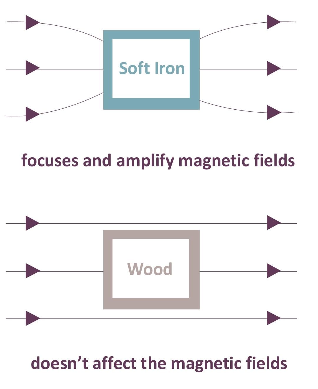
Figure 6
We denote μr as the relative permeability compared to free space (μ0 = 4π x 10-7 Henry/meter).
μr = μ/μ0 (The relative permeability of free space is μr = 1)
Different types of permeability can be identified based on the characteristics of changes in B and H, where H represents the magnetic field strength in amperes per meter. The relationship between magnetic permeability and this change is described by a formula:
μ = ΔB/ΔH
The relative permeability (μferro) of magnetic materials (ferromagnets) is significantly greater than that of non-magnetic materials such as vacuum (μvac), diamagnets (μdia), paramagnets (μpara), and superconductors (μsup) (see Figure 7). [8]

Figure 7
In simpler terms, ferromagnetic materials are ideal for constructing an electromagnet. This works best when they are operating below the saturation point, where the relative permeability is at its peak (see Figure 8).

Figure 8
We can observe that the permeability of ferromagnetic materials decreases as they approach saturation, and this relationship is non-linear with the applied excitation.
Calculations and Discussion
The previous calculation shows that we need a magnetic flux density of 0.2 Tesla [4] based on the following formulas:
r = √(2 x m x U ⁄ q x B2)
v = √(2 x q x U ⁄ m)
Where r is the radius of curvature and v is the velocity. We have found that for B = 0.2 Tesla and U = 300 V, the velocity will be provided in the following table:
| Type of gas | Mass m (Kg) | Radius r (m) | Velocity v (m/s) |
| HCL | 5.76 x 10⁻²⁶ | 0.073 | 40.8 x 10³ |
| HF | 3.2 x 10⁻²⁶ | 0.056 | 54.7 x 10³ |
| SO2 | 10.24 x 10⁻²⁶ | 0.098 | 30.6 x 10³ |
| Hg | 32 x 10-26 | 0.173 | 17.3 x 10³ |
Since our project focuses on toxic gases, a heavy ion such as lead (Pb), which has a mass of 34 x 10-26 kg, will have a radius of 17.8 cm, exceeding the range (see Figure 9).
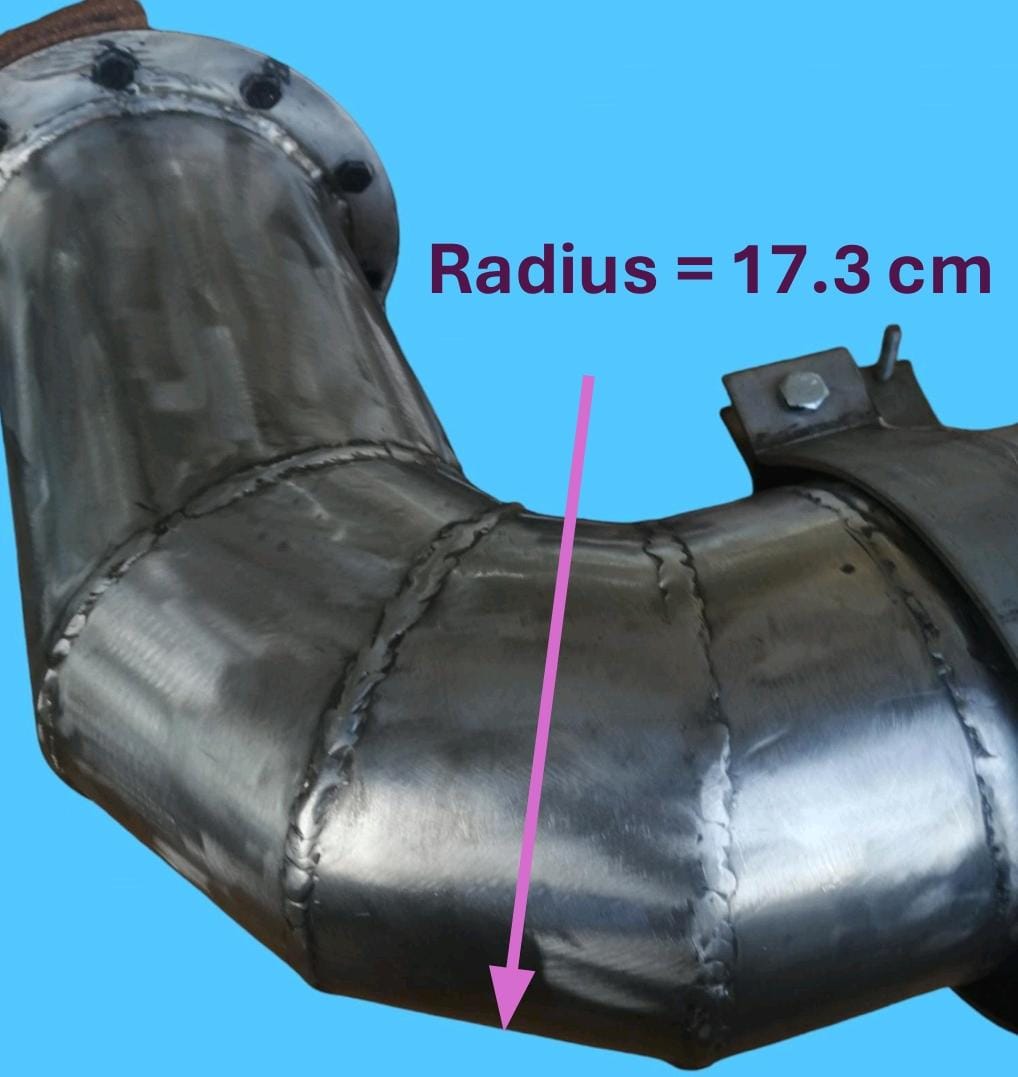
Figure 9
Therefore, we must repeat the calculation to find the ideal solution for the system.
In general, reducing the potential difference and magnetic flux density will enhance the economic benefits of the project. Furthermore, decreasing the magnetic flux density will make the manufacturing of the electromagnet easier and less expensive.
Taking, for example, U = 20 V and B = 0.06 Tesla, gives us the following table:
| Type of gas | Mass m (Kg) | Radius r (m) | Velocity v (m/s) |
| HCL | 5.76 x 10⁻²⁶ | 0.063 | 10.5 x 10³ |
| HF | 3.2 x 10⁻²⁶ | 0.047 | 14.1 x 10³ |
| SO2 | 10.24 x 10⁻²⁶ | 0.084 | 7.9 x 10³ |
| Hg | 32 x 10-26 | 0.149 | 4.4 x 10³ |
| Pb | 34 x 10-26 | 0.153 | 4.3 x 10³ |
Reducing the potential difference will decrease the velocity of the ions in the acceleration zone, but the velocity is still sufficient, as we can observe.
Single Solenoid Coil
A solenoid is essentially a coil of wire, typically made of copper. When an electrical current flows through the wire, it generates a magnetic field, similar to how a magnet works (see Figure 10).

Figure 10
The solenoid often has a cylindrical shape, which helps to create strong and uniform magnetic field.
Despite this, there may be variations in design. Solenoids have the potential to feature a D-shaped frame customized for specific applications. However, the prevailing perception of a solenoid usually corresponds to that of an elongated, cylindrical coil. [16]
Simple Simulation

Figure 11
We used COMSOL Multiphysics to simulate a simple design consisting of a single solenoid with a cylindrical shape (4 cm in diameter and 5 cm in height).
We used 200 turns, a relative permeability of 200, and 6 amperes, and that was the result for the 2D plane (see Figure 11).
The white arrows represent the flow of the magnetic field to determine its direction and uniformity.
We can observe that the maximum magnetic flux density is depicted in red in the center, gradually decreasing in intensity towards blue.
The simulation was conducted again with two solenoids positioned 15 8 cm apart to analyze the magnetic field between them (see Figure 12).

Figure 12
As we can see, the magnetic field is uniform only in the middle, which is insufficient for our application. By employing additional solenoids, we can attain an even more uniform magnetic field.
The simulation indicates that the magnetic field density is insufficient to achieve a 60 mT (0.06 Tesla) strength between the two solenoids.

Figure 13
When we increase the relative permeability to 3000, we observe that the maximum magnetic flux density also increases (4.42 Tesla to 65.9 Tesla) (see Figure 13).
But how can we determine the effect of permeability outside the coils where the relative permeability is one? This will be known after the following simulation.

Figure 14
![]()
Figure 15
We adjusted the scale to a maximum magnetic flux density of one milliTesla (1mT) to display the color distribution outside the coils (see Figure 14). When we reduced the relative permeability to 200, the arrow volumes representing the magnetic fields nearly vanished, suggesting a loss of uniformity (see Figure 15). However, we can see the arrow volumes again by readjusting the arrow scale.
Biot-Savart Law
According to Biot-Savart's law, the magnetic field density at point P, which is on the axis of the center of the solenoid (see Figure16), is equal to:
B = (NIμ) (cosθ1 +cosθ2) /2L

Figure 16
As we observe, cosθ2 is always negative outside the solenoid since θ2 is greater than 90 degrees, while cosθ1 is always positive.
In general, when θ belongs to [0, π], if θ increases, cosθ decreases. Therefore, increasing the radius of the solenoid will decrease the difference between cosθ1 and cosθ2, thus increasing the overall magnetic field.
But the effect of increasing the radius will be negligible for a point far away from the solenoid and at the center of the solenoid since B = NIμ.
Purification of Iron
The purity of iron is an important factor to consider because pure iron is more effective in magnetic fields due to its high permeability.
So, in order to remove impurities from iron, there are several methods, each with its own advantages and disadvantages, to produce pure iron. [9]
We chose to use the electrolytic refining method, which involves an electrolysis cell. The impure iron serves as the anode, while on the cathode side, we use another iron that will be purified. [10]
Needed Materials
Electrolysis Cell
To purify iron, we use an electrolysis cell, which is a container capable of handling the electrolyte solution and separating the anode from the cathode. The container is often made of acrylic.
Power Source
We will need a DC power supply to deliver a constant current with sufficient voltage to drive the electrolysis process. The specific voltage and current requirements will depend on the cell setup and the desired purity of iron.
Impure Iron Anode
The iron you want to purify acts as the anode. The size and shape of the iron will depend on the amount you wish to purify.
Iron Electrolyte Solution
This is a crucial component in the process. Iron(II) chloride (FeCl2) is a popular choice due to its good solubility and availability.
The Cathode
The cathode is where the purified iron will deposit. It is typically made of a thin sheet of iron, which is commercially available as high-purity iron.
The Electrolytic Refining Process
Preparing the electrolysis cell
We fill the cell with an ion electrolyte solution, such as FeCl2 in our case. Then, we submerge the impure iron anode and the cathode into the solution while keeping them separated. To minimize the dissolution of anode material into the cathode compartment, a diaphragm can be utilized.
Applying a DC current
We must connect the power source to the electrodes. The anode will be connected to the positive terminal, while the cathode will be connected to the negative terminal.
Electrolysis
When the current is applied to the cell, chemical reactions occur.
At the anode side, oxidation takes place: Fe → Fe²⁺ + 2e⁻.
The iron atoms from the impure iron anode lose electrons and dissolve into the solution as Fe²⁺ ions.
At the cathode, reduction occurs: Fe²⁺ + 2e⁻ → Fe.
The Fe²⁺ ions from the electrolyte solution gain electrons and deposit on the cathode as pure iron atoms (see Figure 17).
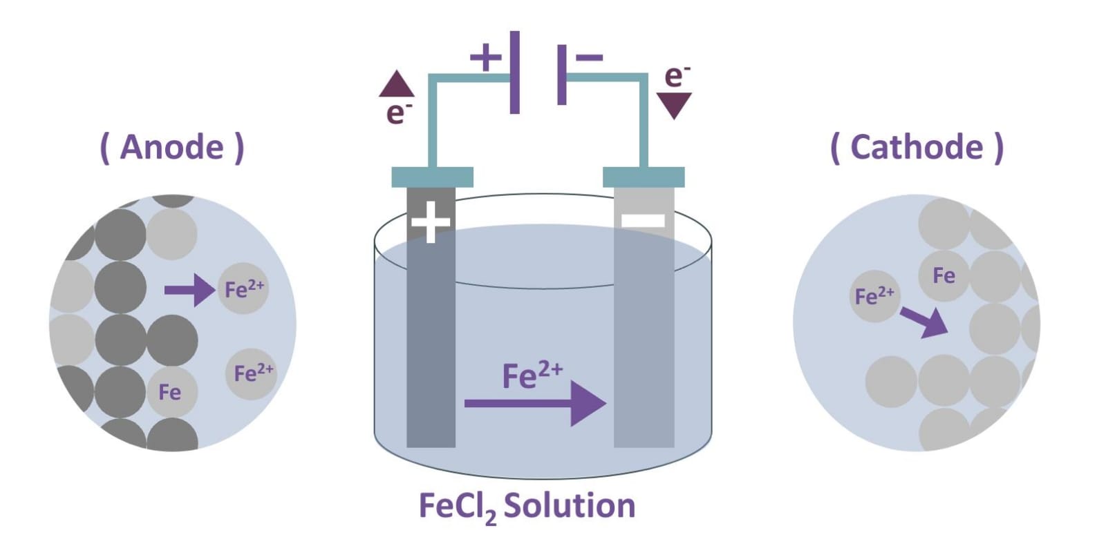
Figure 17
Drawbacks
Electrorefining is technically feasible for small-scale iron purification, but it is not the most practical option for several reasons. It has low efficiency compared to other methods and requires high energy consumption to move the iron ions. In this situation, we either have to use another method of purification or purchase high-purity iron (99.5%) and undergo the electrolytic refining process to achieve even higher purity (99.9%).
Annealing
The annealing process is a heat treatment method used to reduce the hardness and enhance the ductility and toughness of various steels, cast iron, and alloys. This technique involves heating the material above its recrystallisation temperature, which promotes the formation of new grains and enables the reorientation of existing grain structures. [11]
History of annealing
Annealing involves heating to a specific temperature and then cooling at a controlled rate. Historically, annealing was discovered around the 12th century when the word originated from the Middle English term "anelen," which means to set on fire or bake. In Europe, it was discovered through advances in blacksmithing that annealing alters the properties of steel and iron. [12]
Blacksmiths discovered that by heating iron to a specific temperature and then rapidly cooling it, the iron would become stronger and more durable.
The metal heat treatment techniques were developed in the Middle Ages when medieval blacksmiths discovered a process that involved reheating quenched metal to a lower temperature and then cooling it slowly. This enhancement made weapons and armor more effective in wars.
The Industrial Revolution in the 18th and 19th centuries led to the development of the annealing process as we know it today. This process involves heating metal to a high temperature and then allowing it to cool slowly. Subsequently, heat treatment methods have continued to evolve up to the present day. [13]
Annealing Process
The annealing process consists of three distinct stages: an initial recovery phase, a subsequent recrystallisation phase, and a final grain growth phase. [11]
During the recovery phase, a metal is heated to a specific temperature below its melting point using a programmable furnace or oven to regulate the temperature. Typically, nitrogen is purged as an inert gas to prevent the oxidation of the metal. [14]
During the recrystallisation phase, the metal is heated to the desired temperature and held for a specific duration, which varies based on the desired properties. This phase involves the reorganization of the crystal structure and the initiation of new grain structures.
During the grain growth stage, the size of both newly formed and existing grains increases once the cooling process commences. The phase composition, crystal grain size, and growth are determined by factors such as the cooling rate, atmosphere, and material grade (see Figure 18).

Figure 18
Annealing & Permeability
Annealing can enhance the initial magnetic permeability of metals. By subjecting the metals to high temperatures during annealing, the permeability can be significantly increased. The extent of this increase is influenced by various factors, including the temperature applied, the rate of cooling, and the duration of soaking.
Typically, metal permeability increases with higher temperatures, as evidenced by superior results at 1180°C compared to 1093°C. Additionally, longer soaking times contribute to enhanced permeability, with a six-hour hydrogen annealing process yielding higher permeability levels than a two-hour anneal. [15]
References:
[1]: Ahamad, Javed & Ali, Faraat & Sayed, Manjoor & Ahmad, Javed & Nollet, Leo. (2022). Basic Principles and Fundamental Aspects of Mass Spectrometry. 10.1201/9781003091226-2.
[2]: Medhe, S., 2018. Ionization techniques in mass spectrometry: a review. Mass Spectrom Purif Tech, 4(01), p.1000126.
[3]: 4.11: Mass Spectrometry by Pavan M. V. Raja & Andrew R. Barron is licensed CC BY 4.0.
[4]: Asmaa EL MIR, Évolution de dispositif de spectromètre de masse pour la détection des gaz de combustion des déchets municipaux. Master thesis report
[5]: Copy William Harris "How Mass Spectrometry Works" 1 January 1970. HowStuffWorks.com. 22 May 2024
[6]:University of Calgary - Department of chemistry - Mass spectroscopy Ch13 https://www.chem.ucalgary.ca/courses/350/Carey5th/Ch13/ch13-ms.html
[7]: Medhe, Sharad. (2018). Mass Spectrometry: Detectors Review. Annual Review of Chemical and Biomolecular Engineering. 3. 51-58. 10.11648/j.cbe.20180304.11.
[8]: Stan Zurek, Magnetic permeability, Encyclopedia Magnetica, https://www.e-magnetica.pl/doku.php/magnetic_permeability
[9]: Uchikoshi, Masahito, et al. "Metal purification method and metal refinement method." U.S. Patent No. 6,391,081. 21 May 2002.
[10]: Kekesi, Tamas, Kouji Mimura, and Minoru Isshiki. "Ultra-high purification of iron by anion exchange in hydrochloric acid solutions." Hydrometallurgy 63.1 (2002): 1-13.
[11]: Sild, S. (2024, January 26). Annealing Explained – Definition, Process and Benefits. Fractory. https://fractory.com/annealing-explained/
[12]: Annealing: Definition, Purpose, How It Works, and Stages. (2024, June 5). https://www.xometry.com/resources/materials/annealing/
[13]: A Historical Journey Through the Evolution of Metal Heat Treating. (2024, January 1). https://jfheattreatinginc.com/2024/01/a-historical-journey-through-the-evolution-of-metal-heat-treating/
[14]: What Gases Work Best for Annealing? - nexAir. (2022, March 16). nexAir. https://www.nexair.com/learning-center/what-gases-work-best-for-annealing/
[15]: Lin Li, "Controlling annealing and magnetic treatment parameters to achieve high permeabilities in 55 Ni-Fe toroid cores," in IEEE Transactions on Magnetics, vol. 37, no. 4, pp. 2315-2317, July 2001, doi: 10.1109/20.951158.