VaEf Airship
project "alternative Lotte": Project Report (August 2000 � July 2006)
Development
of a Flight Control System for a airship for measuring wind data
Based on student research works of
Samir Mourad, Sven Forstmann, Jamal E., Muhammad
Subhan, Rabih al-Farkh, Nasih Abdelhaqq, Yaser Mikou, Abdelfattah Ammar
Project Manager: Samir Mourad,
Dipl.-Ing. Dipl.-Inform. (MS Sc.
Computer Science, MS Sc. Electrical
Engineering)

Mourad et. al.:
Karlsruhe, July 2006
Ver�ffentlicht von:
Verein f�r alternative
Energieforschung e.V.
Content in
short
Abstract 2
1....... Introduction. 4
2....... Project
Management 5
3....... Flight Control
System of an airship. 6
4....... Optimization
of the Flight Control System architecture. 38
5....... Development of
the Ereignisdienstes for the middleware OSA+. 55
6....... Inertial
Measurement Unit 104
Table of Contents. 105
List of figures: 108
List
of Tables. 112
List
of Tables. 112
Literature. 39
7....... Actuator Board. 41
Table
of Contents. ii
List of figures: vi
Literature. 59
Appendix
A.. 61
ANNEX B.. 67
8....... Communication
and User Interface. 76
Figure 6.6:�
STD-402 Transceiver � CIRCUIT
DESIGN.. 103
Ack Auto Response Setting. 120
Features. 123
�...... Registration of ID.. 142
9....... Annex
D.. 150
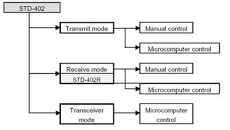
Or the board used to equips the STD-402 is the
MB-STD-RS232, so the� this mode (Auto
Mode Operation Guide for CPU Interface) is used like mode of the STD-402
transceiver. 150
10..... Some repairs
on the sensor card and first step integration. 40
11..... Integration. 73
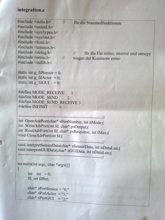
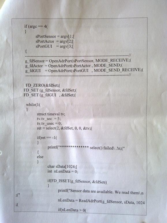
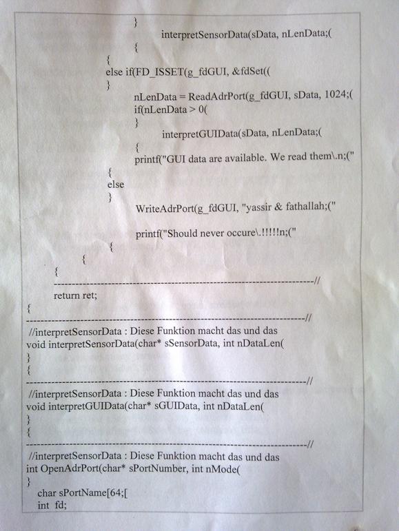
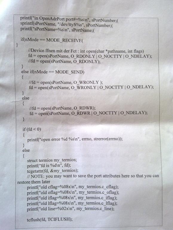
12..... Integration
code in C.. 3
Content
Abstract 2
1....... Introduction. 4
1.1.... The LOTTE
project and the �alternative Lotte�. 4
2....... Project
Management 5
2.1.... Costs. 5
3....... Flight Control
System of an airship. 6
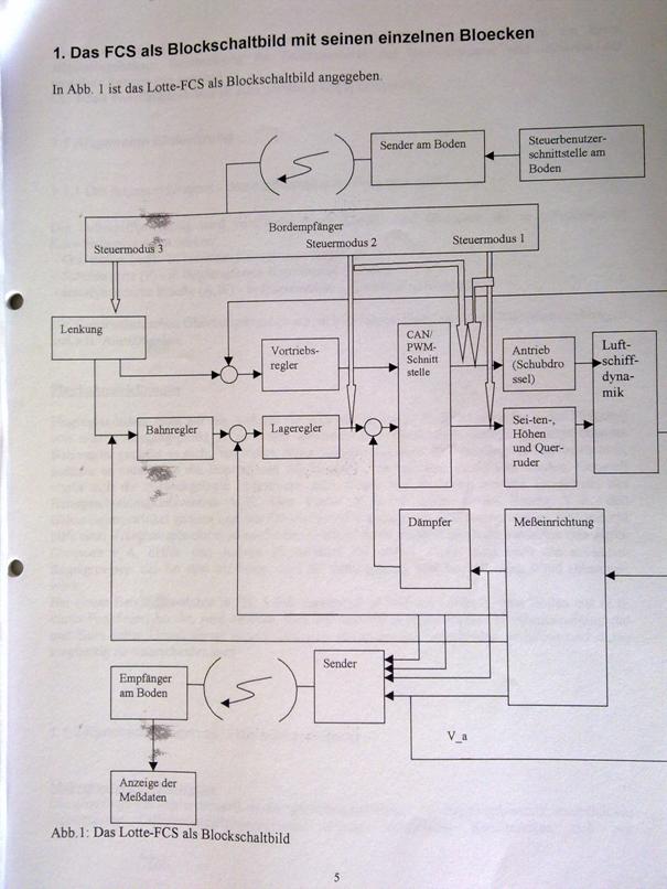
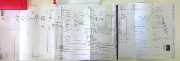
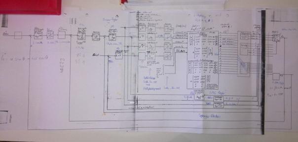
3.1.... Block diagram
of the Control Loops. 37
4....... Optimization
of the Flight Control System architecture. 38
4.1.... The
architecture of the Flight Control System and its simulation on the middleware
OSA+ running on the operating system Windows. 38
4.2.... Results. 39
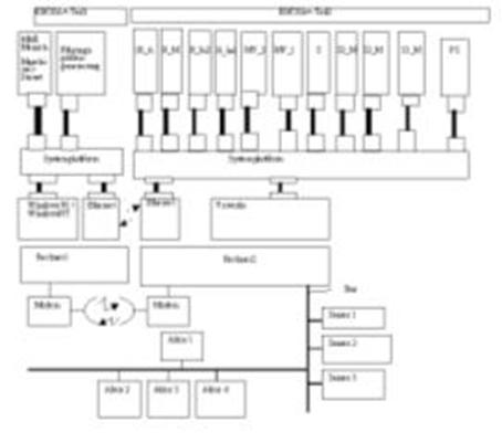
4.2.1.1 System
Architecture of Airship Flight Control System.. 47
4.2.1.2 Simulation
Code (in programming language C) 47
4.2.1.3 Simulation
results. 47
5....... Development of
the Ereignisdienstes for the middleware OSA+. 55
5.1.... Abridged Version. 58
5.2.... The nature of
the task. 58
5.3.... The OSA+ architecture. 58
5.3.1��� Introduction. 59
5.3.2��� The components of OSA+. 60
5.3.2.1 The Platform.. 60
5.3.2.2 Generic Services. 61
5.4.... Components of
the OSA Eventing service. 62
5.4.1��� The time functions. 62
5.4.1.1 The handling
of the time. 62
5.4.1.2 Initialization. 63
5.4.1.3 Functions for time management 65
5.4.2��� The event service. 66
5.4.2.1 General Information. 66
5.4.2.2 The
initialization of the Event Service. 68
5.4.2.3 Features of the Ereignisdienstes. 68
5.5.... Short Overview.. 70
5.5.1��� Time functions/variables. 70
5.5.2��� Features of
the Event Service (Ereignisdienst) 70
5.6.... Configuration. 70
5.7.... Theory of Operation. 72
5.7.1��� Osagettime() 72
5.7.2��� Osasettime(int,int) 72
5.7.3��� Osaaddtime(int,int) 74
5.7.4��� Char * osaPrintTime( int, int ) 74
5.7.5��� Osainitevents() 75
5.7.6��� Int osaAddEvent(uint,uint, uint, uint,uint, uint,uint,
uint, function) 75
5.7.7��� Int
osaDelEvent(uint,uint,uint,UINT) 77
5.7.8��� OSA_Error
osaGetEventResult(uint,UINT) 77
5.7.9��� Internal
functions of the Ereignisdienstes. 78
5.8.... Programming examples. 78
5.8.1��� For example:
Changing the Time. 78
5.8.2��� Example: Add an Event 79
5.8.2.1 Start a
function at a specified time. 79
5.8.2.2 Repeated start a function. 81
5.8.3��� Queries of results. 82
5.8.4��� Delete a Events. 82
5.9.... Test Runs. 83
5.9.1��� Deliver-Test 85
5.9.2��� Test run of a
cyclical events with open. 86
5.9.3��� Test the
maximum temporal resolution on different systems. 89
5.9.3.1 System 1. 89
5.9.3.2 System 2. 92
5.9.3.3 System 3. 94
5.9.4��� Stability tests. 97
5.9.4.1 Exceeding the
maximum acceptable number of Events. 97
5.9.4.2 Exceeding the
maximum acceptable number of events per unit time� 98
5.9.4.3 Overrun of the
events per unit time through Zeituberschneidung. 99
5.10.. Results and Outlook. 102
5.11.. ANNEX.. 103
5.11.1� List of all
Windows specific functions. 103
5.12.. Literature. 103
6....... Inertial
Measurement Unit 104
Table of Contents. 105
List of figures: 108
List
of Tables. 112
List
of Tables. 112
6.1.... Introduction. 1
6.1.1��� Task. 1
6.1.2��� Overview.. 2
6.2.... Basics. 3
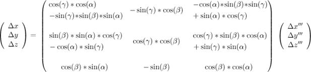
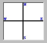
6.2.1��� Coordinate System.. 4
6.2.2��� Calculation of the current position. 5
6.2.3��� Compass. 6
6.3.... Architecture design of the IMU.. 7
6.3.1��� Measurement Data Collection (Me�datenaufnahme) 7
6.3.2��� Measurement Data Processing (Me�datenaufbereitung) 7
6.4.... Development environment 9
6.4.1��� Hardware-Entwicklungsumgebung. 9
6.4.2��� Software Development Environment 10
6.5.... Realization of the IMU.. 11
6.5.1��� Me�datenaufnahme. 11
6.5.1.1 Circuit Design
for the Me�datenaufnahme. 11
6.5.1.2 Reference Voltage. 18
6.5.2��� Board layout
design for the Me�datenaufnahme (Measurement data collection) 19
6.5.3��� Me�datenaufbereitung. 21
6.5.3.1 Circuit Design for the
Me�datenaufbereitung. 22
6.5.4��� Board layout
design for the Me�datenaufbereitung. 24
6.5.4.1 The software for the
Me�datenaufbereitung. 26
6.5.4.2 User Interface. 29
6.6.... Test Results. 33
6.6.1��� Hardware-Test 33
6.7.... Test of
the overall system with the microcontroller (C167) 34
6.7.1��� Gesamtsystem-Test 1. 34
6.7.2��� Gesamtsystem-Test 2. 36
6.7.3��� Gesamtsystem-Test 3. 36
6.8.... Summary and outlook. 38
Literature. 39
7....... Actuator Board. 41
Table
of Contents. ii
List of figures: vi
7.1.... Introduction. 1
7.1.1��� The Solarluftschiff Lotte. 1
7.1.2��� Task. 2
7.1.3��� Overview.. 2
7.2.... Basics. 3
7.2.1��� Real-time systems. 3
7.2.2��� Hardware. 3
7.2.2.1 Components and classifications. 3
7.2.2.2 The microcontroller family C166. 4
7.2.2.3 The C167 microcontroller family. 5
7.2.2.4 The memory
organization of the C167) 6
7.2.2.5 The interrupt
system of the C167) 8
7.2.2.6 The Timereinheiten. 10
7.2.2.7 Capture Compare Unit (Capcom) 11
7.2.2.8 The PWM Pulsweiten-Einheit 13
7.2.2.9 Analog Digital Converter (ADC) 14
7.2.3��� Control of servo motors. 15
7.3.... Architecture
design of the Aktorik-Ansteuerungseinheit (engl, Actuator Control Unit (ACU) 17
7.3.1��� Voltage regulation. 17
7.3.2��� Betriebsspannungsuberwachung. 18
7.3.3��� Basisbetriebszustands-Einstellung. 18
7.3.4��� Steuersignal-Erzeugung. 18
7.3.5��� Notsteuerungsbaugruppe. 19
7.3.6��� Operating conditions of the ACU.. 20
7.3.7��� Modularity of the ACU.. 20
7.4.... Development environment 23
7.4.1��� Hardware-Entwicklungsumgebung. 23
7.4.2��� Software Development Environment 24
7.5.... Realization of the ACU.. 25
7.5.1��� Versorgungsspannungs-Stabilisierung. 25
7.5.1.1 Circuit Design for the Versorgungsspannungs-Stabilisierung. 26
7.5.2��� Betriebsspannungsuberwachung. 28
7.5.3��� Basisbetriebszustands-Einstellung. 29
7.5.3.1 Circuit Design for the
Basisbetriebszustands-Einstellung. 32
7.5.4��� Steuersignal-Erzeugung. 33
7.5.4.1 The hardware
of the Steuersignal-Erzeugung. 36
7.5.4.2 The monitoring
and the forwarding of the PWM-signals from the remote control (normal operation
(B) 36
7.5.4.3 Level 1 Notsteuersignal-Erzeugung. 41
7.5.5��� Notsteuerungsbaugruppe. 44
7.5.5.1 Circuit Design
for the monitoring of the control signals on the output of the ACU and the
channel5-output of the Fernsteuerempfangers. 44
7.5.5.2 Circuit Design for the
Notsteuerungsbaugruppe. 45
7.5.5.3 Circuit Design
for the forwarding of the PWM-signals from Fernsteuerungsempfanger (
Luftschiff-Startphasen -operation) 46
7.5.6��� Layout design of board 1 (
"Voltage regulation", " Basisbetriebszustands-Einstellung "
and " Notsteuerungs-Baugruppe ") 46
7.5.7��� The circuit
boards of the ACU.. 47
7.6.... Experimental results. 49
7.6.1��� Structure of the Testplatzes. 49
7.6.2��� Experiments and test sequence. 50
7.6.3��� The series of tests. 50
7.6.3.1 Test 1. 51
7.6.3.2 Test 2. 52
7.6.3.3 TEST3. 53
7.6.3.4 Test 4. 54
7.6.3.5 Test 5. 55
7.7.... Summary and outlook. 57
Literature. 59
Appendix
A.. 61
ANNEX B.. 67
8....... Communication
and User Interface. 76
8.1.... Introduction. 76
8.1.1��� The LOTTE
project and the �alternative Lotte�. 76
8.1.2��� Development
method. 77
8.1.3��� Working task
and realization approach. 77
8.1.4��� Overview.. 77
8.2.... Basics. 78
8.2.1��� The V-Model 78
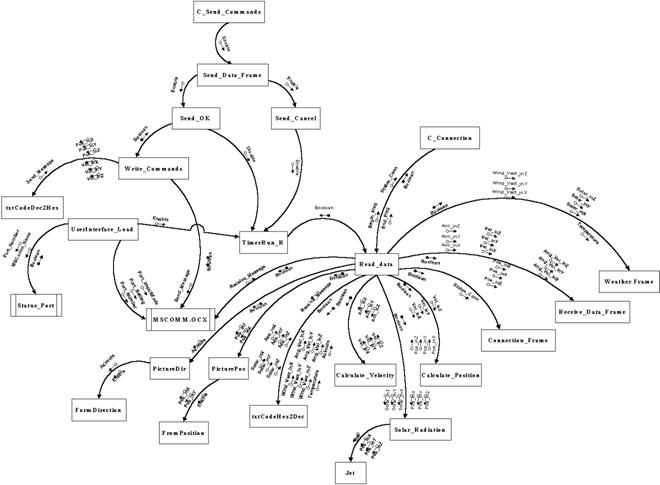
8.2.2��� Structured
Analysis (SA) / Structured Design (SD) 79
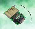
8.2.3��� Transceivers. 81
8.3.... Requirements Specification. 81
8.3.1��� The Graphical User Interface
(GUI) 81
8.3.1.1 Software
Requirements Specification. 82
8.3.2��� Specifications
for the transceiver. 86
8.3.3��� Communication
Protocol for User Data. 86
8.3.4��� Handshaking. 88
8.4.... Architecture Design. 88
8.5.... Development Environments. 90
8.6.... Design and Implementation. 90
8.6.1��� SA / SD and
Implementation for the base station program.. 90
8.6.1.1 SA (Structured
Analysis) 90
8.6.1.2 SD (Structured
Design) 94
8.6.1.3 Implementation. 97
8.6.2��� Communication
part on the board system on the airship. 100
8.6.2.1 The tranceiver. 100
8.6.2.2 The
communication software on the embedded board computer. 105
8.7.... Component Tests. 106
8.7.1��� Transceiver
test 106
8.7.2��� User interface
laboratory test with two PCs. 109
8.7.3��� Test of the
user interface on the target system.. 111
8.8.... Annex A.. 112
8.9.... Annex B. 122
8.9.1��� Block diagram
of the STD-402 transceiver in Direct Mode. 136
8.10.. Annex C.. 137
���������� STD-402TR [Auto Mode
Operation Guide] 137
8.10.1� General 137
8.10.2� Features. 138
8.10.3� Application
Examples. 138
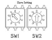
8.10.4� Configuration. 138
�...... Registration of ID.. 142
8.10.5� diagram of the
STD-402 transceiver in Auto Mode. 148
9....... Annex
D.. 150
9.1. 154
9.2.... STD-402 Data Format 154
9.2.1��� Transmitter :
Initial setting flow chart 156
9.2.2��� Receiver: Flow
chart at power ON.. 162
9.3.... Annex E:
Visual Basic code for the user interface program.. 5
9.4.... Annex F: C program code. 32
9.5.... Annex G.. 36
10..... Some repairs
on the sensor card and first step integration. 40
11..... Integration. 73
11.1.. Abstract 73
11.2.. Introduction. 77
11.2.1� The
Lotte-Projekt and the "alternative Lotte". 77
11.3.. Development environment 79
11.4.. Architecture Design and Implementation. 80
11.5.. Literature. 1
12..... Integration
code in C.. 3
ijk
Abstract
In this project report the "alternative Lotte" airship flight
control system project and its results for August 2000 � July 2006 are described.
In summer 2006 the project was cancelled.
The alternative Lotte project aimed to improve the flight control system
of the solar airship "Lotte" of University of Stuttgart.
|
|
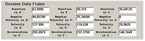
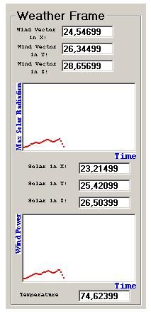
 The user interface is the link
between the user and the alternative � LOTTE, a measurement vehicle for solar
radiation and wind power. Its purpose is allowing the user to control the
alternative� � LOTTE from the base
station, so by using the User Interface, the user can set data to the
alternative � LOTTE (new position, new velocity ...) and get data from the
alternative � LOTTE (acceleration, angular velocity, azimuth, temperature,
wind vector, Solar radiation ...). The user interface is the link
between the user and the alternative � LOTTE, a measurement vehicle for solar
radiation and wind power. Its purpose is allowing the user to control the
alternative� � LOTTE from the base
station, so by using the User Interface, the user can set data to the
alternative � LOTTE (new position, new velocity ...) and get data from the
alternative � LOTTE (acceleration, angular velocity, azimuth, temperature,
wind vector, Solar radiation ...).
|
|
The airship can be controlled from the ground or fly automatically to
specified coordinates.
|
|
|
Airships are becoming more and more important within
the last years. At the �Institut f�r Statik und Dynamik der Luft- und
Raumfahrtkonstruktion� at the University
of Stuttgart a solar
airship was built. In February 1992 the project �Solarluftboot� was initiated.
The purpose of this project was to find new materials, new construction methods
and a new concept for controlling and navigating an airship run by a solar
energy engine.
The �alternative Lotte� � a cooperation project
between the universities of Karlsruhe and Stuttgart and the
Fachhochschule Karlsruhe - is planned to be an experimental airship which can
be controlled directly from the ground (first step of implementation) or
(second step of implementation) fly automatically to specified coordinates. The
energy supply is going to be conventional batteries in the first step but it is
planned to switch to solar energy later. With �alternative Lotte� environmental
data are collected during the flight via different sensors which can be mounted
on the airship. In the first step the speed of the wind, the temperature and the
solar radiation are measured. Apart from that flight data such as acceleration,
angular velocity and azimuth angle are measured for navigation purposes.
For the
above mentioned Solarluftschiff an alternative flight control system (flight
control system - FCS) is developed, which takes into account modern information
technology methods.
The
"alternative LOTTE" project is lead by the association VaEF e.V. As
cooperation main cooperation partners act the Universities of Karlsruhe and Stuttgart. The
"alternative LOTTE" project intends to use an airship for taking wind
measurement data.
Personal
costs: About 3 man years
Material
costs: 6000 EUR
Renting
rooms, computers etc. 10 000 EUR
The project
was undergone through student research works (mostly master thesises).
 This Flight Control System is based on the IFR
Control System of the Lotte airship of the University
of� Stuttgart
/ Germany
This Flight Control System is based on the IFR
Control System of the Lotte airship of the University
of� Stuttgart
/ Germany


Based on:
Samir
Mourad, Diplomarbeit (Master
Thesis)�Anbindung des Echtzeitbetriebssystems VxWorks an die Middleware OSA+
und Integration dessen in eine dienstorientierte
Test-Echtzeitsystem-Umgebung"
Institut f�r
Mikrorechner und Automation, Univ. Karlsruhe, Supervisor: Prof. Dr. U.
Brinkschulte�, Institut f�r Prozessrechnentechnik und Robotik, Faculty of Computer Science, Universit�t Karlsruhe (TH),
December 2000
�berblick
1. Einleitung
Allgemeingehaltene
Einf�hrung in den Aufbau von Echtzeitsystemen. Anforderungen an heutige
Echtzeitsysteme: Rechtzeitigkeit der Verarbeitung, wiederverwendbarer Aufbau
des Gesamtsystems. M�gliche L�sung: dienstorientierter Aufbau (modular,
einfache Erweiterbarkeit des Echtzeitsystems, gibt nat�rlich den funktionalen
Ablauf bei einem Echtzeitsystem wieder) mit Middleware (Trennung von
Anwendungssoftware und Betriebssystem bzw. Hardware)
2. Aufgabenstellung
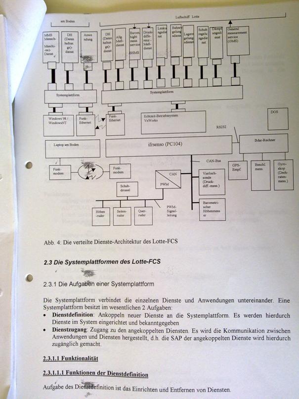
und L�sungsansatz
2.1 Aufgabe
Erstellung eines
dienstorientierten Test-Echtzeitsystem mit zwei Rechnern, die mit Funk-Ethernet
verbunden sind. Der zweite Rechner hat einen CAN-Bus, an dem Sensoren und
Aktoren h�ngen. �ber Funkethernet gibt der erste Rechner dem zweiten Rechner
Anweisungen bez�glich der Bedienung der Sensoren und Aktoren. In die andere
Richtung werden Me�daten �bertragen und auf einer Oberfl�che des ersten
Rechners dargestellt.
2.2 Vorstellung
einiger vorhandener Systeme
2.2 L�sungsansatz
dienstorientierter
Systemaufbau (siehe entsprechende Abbildung in Lottefcs_vom_Leptop.doc)
Begr�ndung f�r die
Auswahl von VxWorks: relativ einfache Handhabbarkeit wegen umfangreicher Entwicklungsumgebung,
in der Praxis erprobtes Standard-RTOS.
3. OSA+
Beschreibung von
Proze�dienst, Ereignisdienst (SA von Sven), Kommunikationsdienst und
Datenhaltungsdienst� (Zusammenfassung aus
Institutsbericht)
4. VxWorks
Vorstellung des Basic
OS,� des I/O System, des lokalen
Filesystems und des Kommunikationssystems (Zusammenfassung aus Programmer's
Guide)
5. Anpassung von
VxWorks an OSA+
5.1 Proze�dienst
5.2 Ereignisdienst (SA
von Sven)
5.3
Kommunikationsdienst
6. Integration ins
Gesamtsystem
Beschreibung der
Dienste, der Treiber, der HW und des Zusammenspiels des Gesamtsystem
6.1 Oberfl�che des 1.
Rechners und zugeh�rige Dienste
6.2
Kommunikationsdienst zwischen 1. und 2. Rechner
6.3 Me�dienste und
Stelldienste auf 2. Rechner
6.4 Treiber f�r VxWorks
bzgl. CAN-Bus (DA von M. Subhan)
(6.5 Sensoren/Aktoren
auf dem CAN-Bus)
7. Ausblick
Variierungsm�glickeiten:
Ersetzung der Sensoren/Aktoren, Austausch des VxWorks durch ein anderes RTOS
bzw. direkte Anbindung an die HW, Ersetzung des Funkethernet durch ein anderes
Protokoll.
Entwicklung einer
verteilten
Experimentalumgebung fuer
die Middleware OSA+
(ESfOSA+)
Diplomarbeit von Samir
Mourad
(Inhaltsverzeichnis)
1. Aufgabenstellung
Thema der Arbeit ist die Entwicklung eines Experimentalsystems
fuer die OSA+-Anbindung an Windows NT und die die darauffolgende
Durchfuehrung und Dokumentation von Test mit diesem Experimentalsystem.
Das Experimentalsystem wird im folgenden mit EsfOSA+
(Experimentalsystem fuer OSA+) bezeichnet.
EsfOSA+ soll eine Simaulation eines embedded system
werden, wobei die Hardwarekomponenten wie Aktoren und Sensoren als digitale
Uebertragungsglieder simuliert werden.
]Der Kern von EsfOSA+ ist komplexer
Regelkreis, der eine zu automatisierende Anlage regelt.
Ausgangspunkt war ein der vorliegenden Arbeit ist
ein analoger Regelkreis, welcher digitaliert wurde und in
dienstorientierter Struktur realisiert wurde. Die Dienste sollen auf der
Middleware OSA+ ablaufen.
Es soll getestet warden, ob es Bedingungen
gibt, unter denen eine solche Regelkreisimplementierung unter OSA+/Windows NT
echtzeitfaehig ablaufen kann.
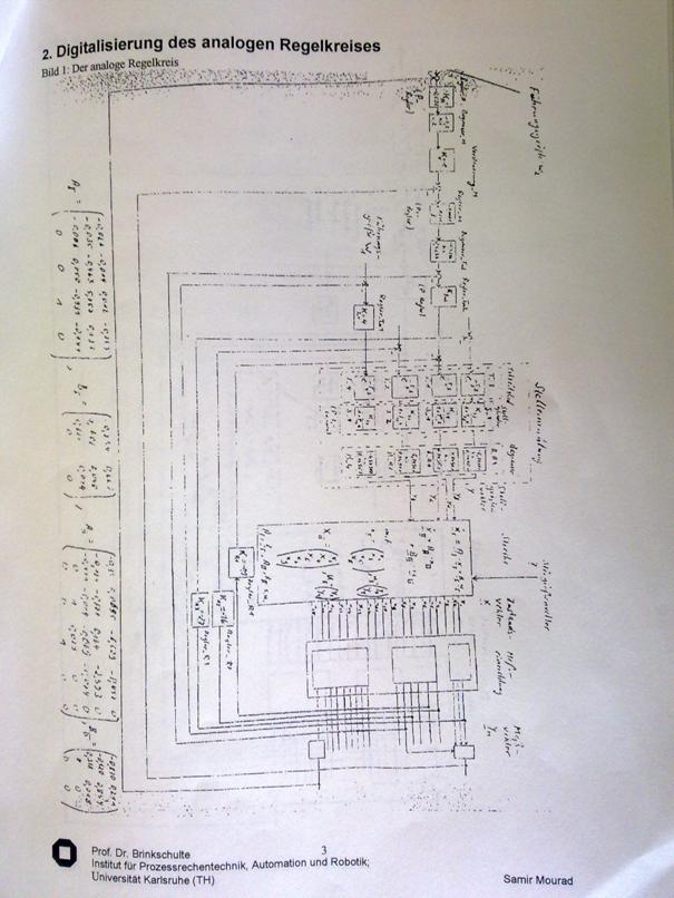
2. Digitalisierung des analogen Regelkreises
Bild 1: Der analoge Regelkreis
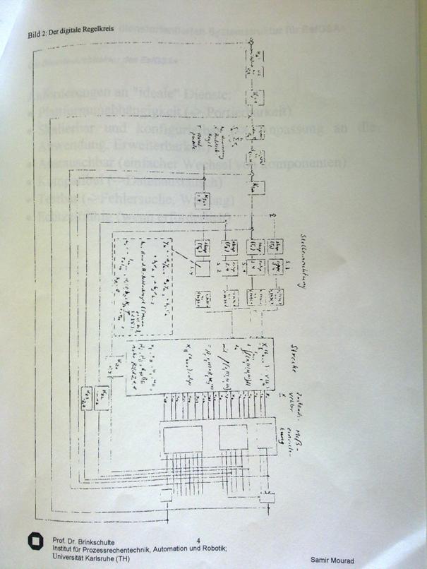
Bild 2: Der digitale Regelkreis
3. Konstruktion der dienstorientierten Systemstruktur
fuer EsfOSA+
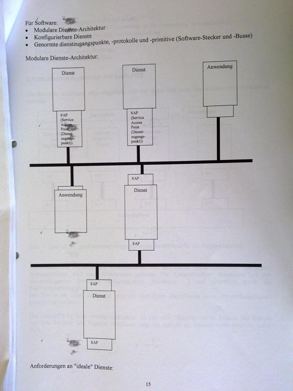
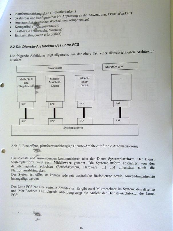
Die Dienste-Architektur des EsfOSA+
Anforderungen an "ideale" Dienste:
* Plattformunabhaengigkeit (-> Portierbarkeit)
*Skalierbar und
Konfigurierbar (-> Anpassung an die Anwendung, Erweiterbarkeit)
* Austauschbar (einfacher Wechsel von Komponenten)
* Kompatibel (->Datenaustausch)
* Testbar (->Fehlehrsuche, Wartung)
* Echtzeitfaehig (Wenn erforderlich)
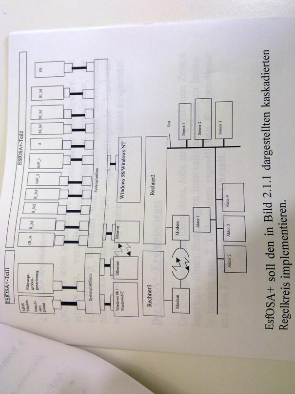
EsfOSA+ soll den in Bild 2.1.1 dargestellten
Kaskadierten Regelkreis implementieren.
4. Die OSA+ Architektur
OSA+ ist eine skalierbare echtzeitfaehige Middleware.
Sie erlaubt es, verteilte Anwendungen zu entwickeln, die echtzeitfaehig
ablaufen und innerhalb eines heterogenen Netzwerks existieren. Die
zugrundeliegende Hardware sowie die Betriebssysteme warden dazu optimal ausgenutzt.
Der OSA+-Ereignisdienst
Der Ereignisdienst dient dazu, Jobs zu vorgegebenen
Zeiten innerhalb eines festgelegten Intervalls ausfuehren zu lassen. Er besteht
aus 2 Teilen: dem eigentlichen Ereignisdienst und den Funktionen fuer
die Uhrzeit.
5. Experimentelle Ergebnisse
5.1 Die
Simulationshardware
Die Simulation life auf einem PC mit einem Intel
Pentium Prozessor mit 133 MHz und 32 MB RAM ab.
Sensorik und Aktorik wurden softwaremaessig simuliert.
Es war keinerlei reale Sensorik oder Aktorik angeschlossen.
5.2 Die
Testreihe
Bei den Tests wurden verschiedene Dienste eingesteckt
und das Zusammenspiel getestet. Dabei wurde so vorgegangen, dass zunaechst nur
die Dienste der inneren Regelschleifen mit den zugehoerigen Messdiensten und
natuerlich der Streckensimulation und des Stelldienstes eingesteckt wurden.
Spaeter wird sukzessive der ganze kaskadierte Regelkreis von innen nach aussen
aufgebaut.
Einstecken von
PS, S1_M, S2_M, S, R_In1, R_In2
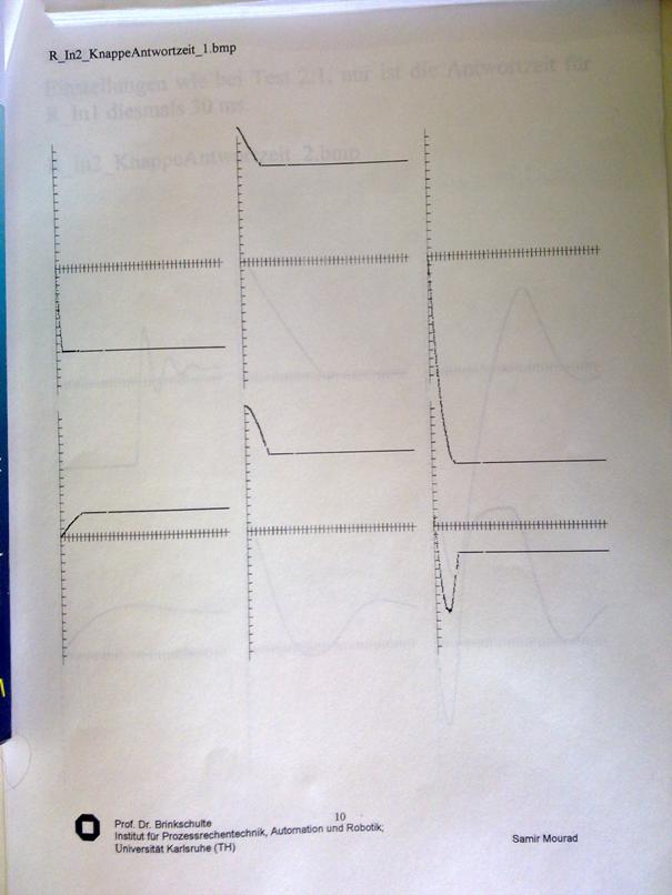
Test 2.1
Festlegung der max. Antwortzeiten der einzelnen Dienste
(durch den Ereignesdienst)
PS���������������������� 10ms
R_In1����������������������� 20ms
R_In2������������������������ 100ms
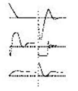
Wie schon im vorigen Test warden einige Groessen ueber
der Zeit aufgezeichnet (Graphen von links nach rechts):
y_4, x_1,
x_5, x_12, x_8, y_1,, (d.h. der 1.
Graph v. l. zeigt y_4, der 2. Graph v. l. zeigt x_1 usw.)
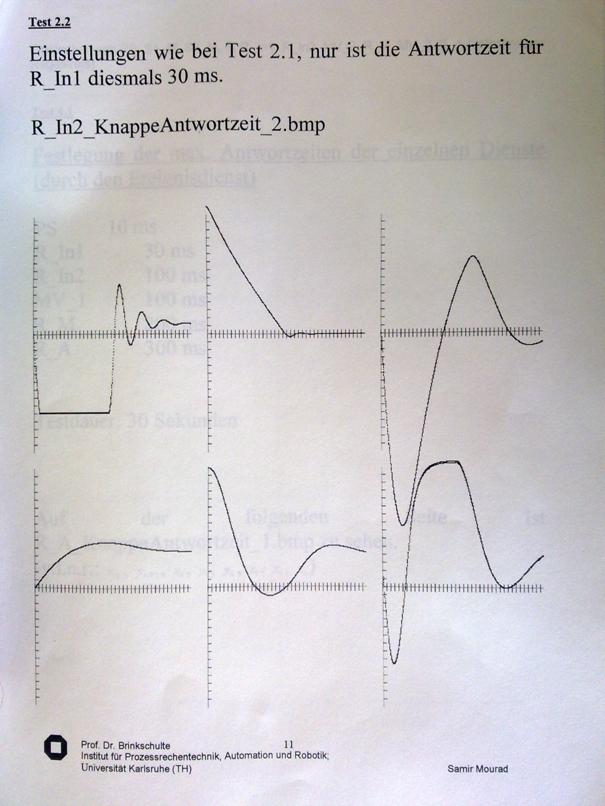
Im Bild R_In2_KnappeAntwortzeit_1.bmp ist zu sehen,
dass die Dienste nicht vollstaendig ausgefuehrt warden konnten. Im naechsten
Versuch (siehe R_In2_KnappeAntwortzeit_2.bmp) wird daher die Antwortzeit fuer
R_In1 erhoeht.
R_In2_KnappeAntwortzeit_1.bmp
Test 2.2
Einstellungen wie bei Test 2.1, nur ist die
Antwortzeit fuer R_In1 diesmals 30 ms.
R_In2_KnappeAntwortzeit_2.bmp
Einstecken von
PS, S1_M, S2_M, S, R_In1, R_In2, MV,_2, R_M, MV_2, R_A (vollstaendiger
Regelkreis)
Test 4.1
Festlegung der max. Antwortzeiten der einzelnen
Dienste (durch den Ereignisdienst)
PS�������� 10 ms
R_In1����������� 30 ms
R_In2������������ 100 ms
MV_1���������� ��100 ms
R_M��������������� 200 ms
R_A��������������� 300 ms
Testdauer: 30 Sekunden
Auf der folgenden Seite ist
R_A_KnappeAntwortzeit_1.bmp zu sehen.
(v.l.n.r.: x_12, y_MV1, x_8, y_1, y_4, x_1, x_3,
x_5)
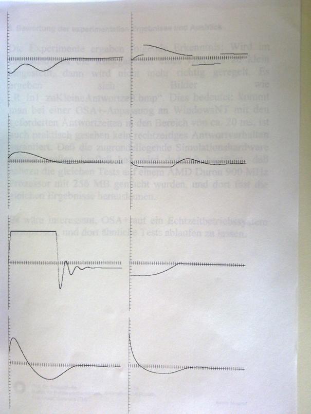
�6. Bewertung der experimentellen Ergebnisse und
Ausblick
Die Experimente ergaben folgende Erkenntnis: Wird im
Ereignisdienst die Rueckgabezeit eines Dienstes zu klein eingestellt, dann wird
nicht mehr richtig gereglt. Es ergeben sich Bilder wie
"R_In1_zuKleineAntwortzeit.bmp". Dies bedeutet: kommt man bei einer
OSA+-Anpassung an WindowsNT mit den geforderten Antwortzeiten in den Bereich
von ca. 20 ms, ist auch praktisch gesehen kein rechtzeitiges Antwortverhalten
garantiert. Dass die zugrundeliegende Simulationshardware keinen grossen Einfluss
hat, wird dadurch bestaetigt, dass nahezu die gleichen Tests auf einem AMD
Duron 900 MHz Prozessor mit 256 MB gemacht wurden, und dort fast die gleichen
Ergebnisse herauskamen.
Es waere interessant, OSA+ auf ein
Echtzeitbetriebssystem anzupassen, und dort aehnliche Tests ablaufen zu lassen.
Based on Entwicklung des Ereignisdienstes
f�r die Middleware OSA+, Studienarbeit von Sven Forstmann, 2001
Studienarbeit
(Bachelor Thesis)
of
Sven
Forstmann
27 Sep 2001
Institute for
Proze�rechentechnik and automation, Univ. Karlsruhe
Supervisors:
Samir Mourad
Dipl. -Inform. Jens
Riemschneider
Prof. Dr. Uwe Brinkschulte
1������� Abridged
Version. 4
2������� The nature of
the task. 4
3������� The OSA+
architecture. 4
3.1���� Introduction. 5
3.2���� The components of OSA+. 6
3.2.1... The Platform.. 6
3.2.2... Generic Services. 7
4������� Components of
the OSA Eventing service. 8
4.1���� The time functions. 8
4.1.1... The handling of the time. 8
4.1.2... Initialization. 9
4.1.3... Functions for time management 10
4.1.3.1 Time
Continued. 10
4.1.3.2 Reading
Time. 11
4.1.3.3 Move
Time. 11
4.1.3.4 Spend
time in a string. 11
4.2���� The event service. 12
4.2.1... General Information. 12
4.2.2... The initialization of the Ereignisdienstes. 14
4.2.3... Features of the Ereignisdienstes. 14
4.2.3.1 Add
an Event 14
4.2.3.2 Remove
a Events. 15
4.2.3.3 Reading
a result/error codes. 15
5������� Short Overview.. 16
5.1���� Time functions/variables. 16
5.2���� Features of the Ereignisdienstes. 16
6������� Configuration. 16
7������� Theory of
Operation. 17
7.1���� Osagettime() 17
7.2���� Osasettime(int,int) 17
7.3���� Osaaddtime(int,int) 18
7.4���� Char * osaPrintTime( int, int ) 18
7.5���� Osainitevents() 18
7.6���� Int osaAddEvent(uint,uint, uint, uint,uint, uint,uint,
uint, function) 18
7.7���� Int osaDelEvent(uint,uint,uint,UINT) 20
7.8���� OSA_Error osaGetEventResult(uint,UINT) 20
7.9���� Internal functions of the
Ereignisdienstes. 21
8������� Programming
examples. 21
8.1���� For example: Changing the Time. 21
8.2���� Example: Add an Event 22
8.2.1... Start a
function at a specified time. 22
8.2.2... Repeated start a function. 23
8.3���� Queries of results. 23
8.4���� Delete a Events. 24
9������� Test Runs. 25
9.1���� Deliver-Test 26
9.2���� Test run of a cyclical events with
open. 27
9.3���� Test the maximum temporal resolution
on different systems. 28
9.3.1... System 1. 28
9.3.2... System 2. 30
9.3.3... System 3. 32
9.4���� Stability tests. 34
9.4.1... Exceeding the
maximum acceptable number of Events. 34
9.4.2... Exceeding the
maximum acceptable number of events per unit time. 34
9.4.3... Overrun of the
events per unit time through Zeituberschneidung. 35
10����� Results and
Outlook. 37
11����� ANNEX.. 38
11.1�� List of all Windowsspezifischen
Functions. 38
12����� Literature. 38
Declaration
I hereby declare, Sven Forstmann, that I have carried
out this work independently.
Thanksgiving
First of all, I wish to thank Prof. Brinkschulte for
the nice assistance and cooperation and also thank Jens Riemschneider for
assistance during the incorporation in OSA+. Samir Mourad was for the friendly
help thanked in advance of the thesis.
Middleware systems support the development of
real-time systems especially in heterogeneous environments, in the present work
is the event service with all the details, as well as the
Implementationsbeschreibung presented.
The event service extends the existing OSA+ to
services for the timed start jobs or functions, as well as to several functions
to manage the time.
What is important is that the Ereignisdienstes the
OSA+ now one step closer in the direction of the real-time capability brings,
this is achieved by, inter alia, that when you start a job / a function also
can be specified, in which interval This is to be started, however, the extent
to which this real-time capability achieved will depend on the respective
operating system, and is also by the handling of the time functions of the same
limited.
In the framework of a joint project with several
industrial partners, the Institute for Proze�rechentechnik and Automation the
open, scalable, and real-time middleware platform OSA+ (Open System
Architecture Platform for universal services) developed, today's real-time
systems usually operate in environments with many asynchronous events, and the
processing of these events is often complex and may, by the introduction of a
own service established for this purpose will be much easier. The aim of this
thesis is the design of the service, a prototypical implementation and
integration into the OSA+ overall architecture.
The content of this chapter is [Brinks et al, 00] taken
from the description of the individual OSA+ -functions from [Brinks et al, 00]
are not listed, it can be read there.
OSA+ is a scalable real-time middleware that allows to
develop distributed applications, the real timable expire and exist within
a heterogeneous network. The underlying hardware, as well as the operating
systems to be used optimally.
The architecture of OSA+ is divided by a application
in services that communicate with each other on jobs, this communication is
achieved by means of a platform, in which services in the platform
"Plugged in", in this way can inserted into all services with one
another using the Platform communicate.
The platform itself specifically used excellent
services, to increase its capabilities, including generic services, which
ensure that the platform independent of the operating system and the underlying
hardware, it is, as well as Erweiterungsdienste, the specific tasks for the
platform provide the platform is, however, also run without these services.
The following is the detailed architecture described
by the OSA+.
1: OSA+ architecture
2:
Communication of services using job and outcome ( =job)
First, it is described as the "naked"
platform looks like and what functionality it provides, so that you will be the
base and Erweiterungsdienste explains and the associated additional
possibilities, thus acquires the the platform, and concludes the interfaces of
the platform and the basic and Erweiterungdienste described.
The platform is the component to the user by the OSA+
is visible, it offers a interface, with whose assistance services in the
platform can be inserted and allowed the grant of orders, which is divided the
platform in three basic parts:
�
A Service Management:
she knows all inserted services and completed the install and
uninstall services, as well as locate of services;
�
A job
management: Allows the give and expect of orders and the report of
results of this and expect orders;
�
A user
interface: Is there a clear struktierte the user interface to
these two bodies.
The platform uses the generic services, to an
encapsulation of the operating system functions, which you can use for your
tasks are not generic services installed in the platform, so must the platform
without these features and can only get to make, what as a recognized standard
of the underlying implementation language is recognized, based on the
ANSI-Richtlilien for C and C++ or the JDK 1.0 . Beyond functionality of the
generic services must be available in each are this:
�
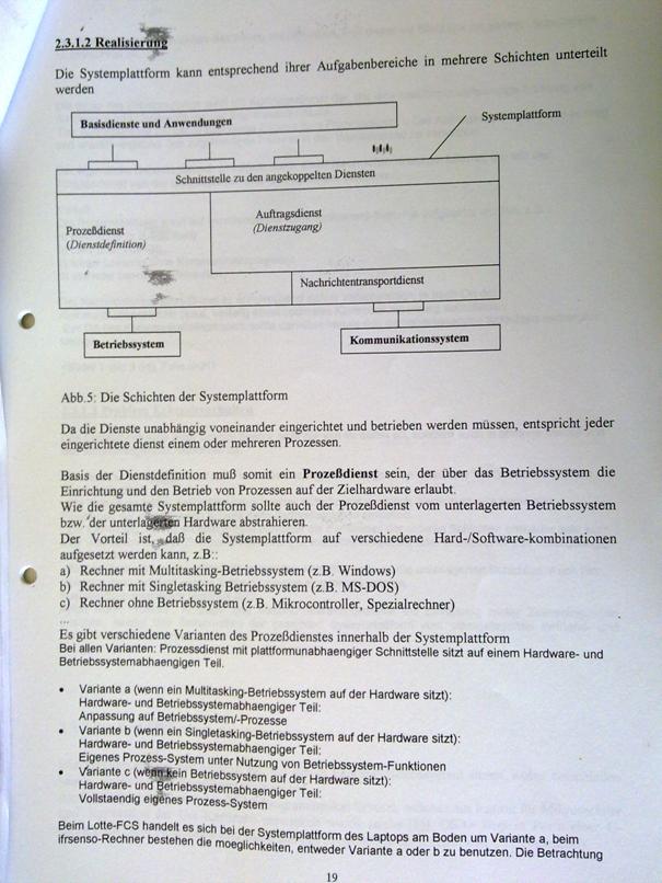
Proze�dienst: it allows the
platform lightweight and/or heavyweight to take advantage of services, he
provides a unified interface to process administration of the operating system,
and the OSA+ -Proze�dienst allows it, split the control flow of the customer,
so that the contractor and the customer (quasi) in parallel, each with their
Arbeitfortfahren can. This is possible, that of the Proze�dienst the platform
allowed, with a service to connect a Control Flow, heavyweight Kontrollflusse
are situated in their own space and are in need of a Miniplattform, on the A
Kmmunikationsdienst (IPC-service) is installed.
�
Echtzeitspeicherdienst: it allows the
realtime access to memory (in particular the allocation and release), not
real-time memory is in the above language specifications standardized (e.g.
malloc in C or new in C++ or Java). The service is not installed, so the time
conditions are checked only a job, but not guaranteed.
�
Communications services: serve the platform
to the shipping of orders over any communication media, it is also the
Interprocess Communication as a means of communication.
�
Eventing service: is the
platform for the monitoring and control of temporal processes. He provides
specific Auftragspezielle jobs to the platform, so this on certain events can
be informed.
The event service is divided into the services for the
management of the time, as well as in the of the actual Ereignisdienstes. a
separation of these two is not impossible, but awkward, as the event service on
the functions of the time is dependent on time, to all the processes to start.
In the event service is managed the time in the UNIX
FORMAT, as this is the easiest to handle, and at the same time the
implementation on UNIX/LINUX - systems much easier.
In this format, the seconds since 1.1.1970 12:00:00 in
a 32 ( soon, perhaps even 64 ) bit - value paid, which means that extra for
Sekunde/Minute/Stunde/ ... not a variable is needed, and also that the invoices
are carried out with the time, are now almost easily.
In the OSA-event Service is the time but now not only
in a 32-bit value, since there often also in real-time applications to a higher
accuracy is essential, therefore it is in addition to the 32-bit variables for
the seconds a further variable used for the milliseconds. This makes it
difficult and slows down while the calculation of time differences, but it is
for the time-exactly timed execution of the job is essential.
It could also have been upgrading the CMOS-clock for
all of the operations of the time, as well as to use of the Ereignisdienstes -
this had caused some complications, however, first of all it is not accurate
enough, because you only on the time the tenth stores, since the event service
is to be real timable and there you have a accuracy is promoted in the
millisecond range, this is enough and not from, a further difficulty is that
when the time change this change affects the entire system and be influenced by
other programs, then what in these can create incorrect results.
3: Structure of the time
4:
Integration of time management, and in the system of the Ereignisdienstes
Before the time functions that can be called the
initialization must be performed first, which for the time periods
required calculated variables.
This calculation is necessary, because the time with
the help of two different functions is calculated.
With the A
is initially read out the time of the system and stored in the time variable,
since the system time but only on the second exactly is returned, only to a
Sekundenwechsel must be serviced to ensure the Millisekundenanteil can be
initialized with zero.
Now, the difference to the value of the other function
are calculated, which returns the system time in Millisekundenformat. In this
is the number of milliseconds since the start of the system, since you can get
with this 32-bit value but only 2 ^32 milliseconds can be used to specify,
which corresponds to 49.71 days, you can use this function only to do this,
read the time already with the help of this function to update, and is now an
offset is calculated at the beginning of the system time and always corresponds
to the difference of Millisekundenanteil indicating to system time.
In addition, the initialization of the time and also
the Ereignisdienstes starting values for the set, in order to save another
function call.

5: PAP of the time initialization
When you set the time, the global time variable
updated for seconds, and milliseconds. This also takes into account whether
Millisekundenanteile have been specified, the Not in the range 0 to 999. In
this case, a carryover for the seconds portion of is calculated, and the
Millisekundenanteil corrected accordingly.
But it is only the time of the OSA+ internally changed
- the general CMOS clock of the computer remains untouched.
The time periods necessary to offset the difference
between milliseconds of the system and the real time, must also be newly set so
that it does not come to the wrong calculations.
When reading the time, the global variable for
seconds and milliseconds updated. For this purpose, the difference in
milliseconds since the last time the query with the help of the system time
calculated and added to the current time.
Since the system time to calculate is used, it should
in fact not later than 49 days all the time query be invoked once, but now that
the event service is associated with the time, it can be ausgegeangen that this
due to its timer is called more often, in order to start the events correctly,
it must also of course at each time, in the course of which he is called from
the timer, the time queries, which is now the reason for this, that the time of
an application program does not necessarily have to be called regularly.
6: PAP of
the time
This function adds to the current time a specified
time difference in addition to this, in principle, this function does not have
been necessary, since one with the two above functions exactly the same thing
can reach had - but so is now saved time, and this may be to match the time on
the network can be of use, and the user will work when calculating the
carryover disconnected.
This function creates a string in which the
current date and time is included with milliseconds. ( This is especially handy
in debug output ). This is done by first with the help of the ctime from the
current time, in the 32-bit value is stored, generated a string, the date and
time already contains, the only thing missing now is the Millisekundenanteil,
which simply by various Stringkopieraktionen is inserted.
The event service is responsible for ensuring that
jobs at a specified time with a pre-specified accuracy can be started. He is to
guarantee the real-time capability of the OSA, which but limited by the
underlying operating system is, for jobs be started via the network, must,
however, only the clocks of the two systems are synchronized, this is by a
long-term observation of the Pingzeiten possible; as a result of the time
offset can then be calculated by which the current time has to be postponed, an
alternative would be the average of the Pingzeiten to calculate the last few
minutes, and with this to synchronize the clocks.
The event service is from Geschwindigkeitsgunden
directly in OSA have been implemented, it is therefore not directly to a
LW/HW-service, but rather a supplement to the OSA+ features available.
Figure 7:
Architecture of the Event Service (Ereignisdienst)
The initialization of the Ereignisdienstes is
automatically after the initialization of the time. This is the first to be the
necessary variables for the Eventing service set, the next step is the timer
function of the Ereignisdienstes started, what must be called upon regularly in
order to make it in time to start the jobs, in which intervals this is to be
called, depends on the desired accuracy of the Ereignisdienstes as well as the
speed of the underlying system, try showed that, for example on a Duron 900
even an interval of one millisecond is possible.
On a Pentium 100 products, on the other hand, only
5-10 ms intervals possible. ( but more about that later in the test runs.
It would also be conceivable, the performance of
the Ereignisdienstes to increase that zeitkirtische functions through the
implementation of assembly code are replaced.
When you add new events there are several possibilities:
The job can be either at a specific time, or with a relative delay be
called, and you can also be used to specify whether the job repeatedly in a
certain time interval is to be started (for example, is for the regular queries
of sensors helpful), and whether the result of the delivers to the later check
is to be saved, and also can be a optional to call a function if it
particularly in the short responses to local applications. When you add it can,
however, to get any error messages if the job was already over, the list is
full, or too many jobs at the same time are to be started, and this number in
the same time interval the job to be started is adjustable and should be to the
respective system be adapted to maintain speed and in addition must still be
given a timeout, the constrains the time window in which the job is to be
started.
The job is only called after leaving the window, so
is he skipped ( this happens but only if it to failures or malfunctions in
the system, the calling of the timer function prevent ). If it is a repetitive
job, it will be the next time but started again, and can still be set, if he is
as closely as possible to the Zeitgitter oriented, or the delay as precisely as
possible is to be met.
The Add/delete a job may be to delay a few
milliseconds, since, as long as the interrupt routine is active, no operations
on the list of job to be started are allowed, this of course also applies vice
versa for the interrupt routine, if you an insert/delete operation interrupts,
this call is ignored, which may of course have the consequence that a(IGE)
Event(s) to a few milliseconds late be started - what but only at very slow
computers into the weight cases is expected.
The job that you want to be the Ereignisdienstes in a
circular list managed fixed-size, you can, after you have been added to this
list, also again be removed - if you have not yet been started.
In order to results of the query again later delivers
to, is not yet an additional list managed, in the opened up for each event
to an entry exists (the key is the ID of the job), but for reasons of space is
only for each EventID keep the latest result.
If the size of the lists is to be changed, is that in
the source code simply by changing the #defines in the beginning to reach the files.
In addition, it can not - real-time operating systems
that have come to the timer not in time will be called; the result may be that
the events do not correctly can be started and is currently are then to be
started up to the point that started events at a time, i.e. as long as the
timeout of the respective jobs is not exceeded.
Another difficulty arises if a cyclic job has been
called for, the back is to be added to the list and an error occurs: a time
already past, crowded or list the already too many events to the desired time
be called, in order to solve this problem, is, at the moment a part installed,
the attempts to the event to matureness, later to start dates.
This will be calculated by either, that either the
next possible start times will be taken, or but in the set for the job by
increments is attempted, add the job again, the number of retries can be
adjusted - but should not be set too high, otherwise if there are too many
errors the time interval of the timer not longer sufficient, and the next will
be affected, if the rescue but is unsuccessful, the job will no longer be
called.
Back to an event from the table of the job to be
started to remove, first waited until requests on the table are allowed and
then occupied the semaphore.
The next step will be for the complete table, and
skipped the event you want to delete, and the remaining are automatically
when.
Now here is the error code returned, which when you
start a job is created, it can here, however, from being purged the last result
which emerged only be queried, and internally to a list of all mitzuloggenden
Events kept, in the then at the start of the event the result will be entered,
if there are more events will be logged, as the list is large, after the FI
Fo-Prinzip approach.
UINT osatime: Are Using Unixtime in seconds�����������������������
UINT osamtime: related Millisekundenbruchteil (
<1,000 )��������������
Osagettime: time reading�������������
Osasettime: Time Set��������������������
Osaaddtime: Time-add offset�����������������
Osaprinttime:
Spend time������������
Osainitevents: Initialize event service and Time��������������������
Osadelevent: Delete Job���������������
Osaaddevent: Add Job�����������������
Osageteventresult: Result of a running job reading���
The configuration of the Ereignisdienstes within the
source code can be made, and by modifying the various definitions (
#define) at the beginning of the source code:
( Alternatively, these parameters from the source code
be relocated in the Makefile.
Variable������������������ instantaneous value
propositions���������������
EVENTSPERTIME 5 ���������� :
determines the number of bootable events at the same time
TABLENGTH� ������ 255:
Indicates the size of the Event-Tabelle (must be a 2 ^n-1 number)���
ERRORBUFFER� �� 7 ���������� : Specifies the size of the
Result-Tabelle (must be a 2 ^n-1 number )
RETRYCOUNT�� �� 4 ���������� : specifies how often should be
attempted, a recurring event in the
List should be entered, if errors occur
OSA_DEBUG:
If defined, debug messages are issued, the����������������������������������
All of the important actions of the
Ereignisdienstes describe
Parameters:
None
Input
integer:NONE����������
Reads the current time from and updates the global
time variable ( osatime and osamtime ).
Implementation:
The time is almost to the millisecond, and is
calculated from a combination of the internal clock and the system time, the
clock will be at the beginning needed to fix the start time in seconds, but not
the accuracy is sufficient for OSA as a timer, in that, it not the time to the
millisecond that shows exactly, now here comes the system time in the game, the
milliseconds since the start of Windows in a 32-bit value, and if you now waits
until the clock the seconds count up to 1, then you can use it to calculate a
differential value to system time, and with the help of the value they get the
missing milliseconds for the time.
If so now osaGetTime() is invoked, the milliseconds
updated, and at a value greater than 1,000 according to also the seconds, and
the difference between this and the system time.
Parameters:Seconds,Milliseconds����������
Input
integer:NONE����������
Sets the time seconds is the time in the Unixformat
and milliseconds are the associated thousandth.
However, this change also directly to the events that
are already in the list are entered, and are to be started; i.e. it quickly in
case of major changes can lead to errors.
Implementation:
Here are the global variables are updated;
Millisekundenanteile greater than 999 will be automatically converted in
seconds.
Parameters:Seconds,Milliseconds����������
Input
integer:NONE����������
Added to the current time in addition to the time
difference of the call-up parameters milliseconds greater than 999 will be
converted to the seconds.
( Here are also negative values registered )
Implementation:
This function first reads the time from, and then
added the desired time difference, taking into account a Millisekundenuberlaufs,
added.
Parameters:Seconds and milliseconds of output time�����������
Input integer:String with the date and time.�����
This function returns a pointer to a string, the
current date and time includes, in debug output is very helpful, since also
thousandths of a second to be issued.
Implementation:
The function will access the Function ctime
back, which from a 32-bit value (Epoch) a string with the date and time
calculated. This string will then be modified, so that even milliseconds with
be returned.
Parameters:
None
Input
integer:NONE����������
Initializes the table in which the jobs be entered
later and sets the time.
Implementation:
All of the entries will be first in the list of events
deleted, and the difference between the internal clock and the system time for
osaGetTime determined. The next step is now set the timer, later also the
starts the job, which is the Multimediatimer of Windows, the a function with a
definable accuracy can repeatedly. (image 5)
Parameters:assigned id1,NUMCOUNT ID
2,Type,start,MSTART, repeat,mRepeat, timeout, FUNCTION��������������������������������
Input integer:0 =OK, 1 =list already full, 2 =too many
events to the same Zeit,3 =time is already over��������������������������������
Assigned ID1,NUMCOUNT ID 2:ID's of the job that you
want to (ID1 is the normal ID of a job, ID2 is ����������������������������������
For
the future of applications planned)
Type:Bit 0 =0:Start at the specified time (
Start,MSTART )����������������������������������������
���������������������������������������������� Bit
0 =1:Start in Start.MSTART Seconds�
���������������������������������������������� Bit
1 =0:start only once������
���������������������������������������������� Bit
1 =1:repeatedly at intervals of repeat.Start mRepeat��������
���������������������������������������������� Bit
2 =0:return value of not logging osajbscdDeliver��
Bit
2 =1:return value of osajbscdDeliver log for later queries (costs a little more
time.����������
���������������������������������������������� Bit
3 =0:start times will be respected as precisely as possible����������
Bit
3 =1:time differences are maintained as closely as possible�������
Bit
4 =0:When Retries try,the job to start at the soonest Time����������
Bit
4 =1:In retries the job in time intervals of repeat.Try to start mRepeat�
Start,MSTART:Start at/in Start.MSTART Seconds�������������������
Repeat,mRepeat:If
in type is specified, the event in repeat.mRepeat seconds called again������
TimeoutGibt
the size of the time window, in milliseconds, in which the job is to be
launched
FunctionWenn
not zero, the specified function ( void function() ) called - osajbscdDeliver
is not running in the case���
Adds a job to be launched to the Event List in
addition to this, the function can be specified the optional, but it is only
intended for local use, if short response times are of importance, this feature
is this, that you will be called directly, with the same priority as the timer
function of the Ereignisdienstes started ( on Windows, this is the the highest
). You should therefore not be longer than 1-5 ms to use it, as the
subsequent jobs this can be affected in some circumstances, since a while(1);
in this function, e.g. the system leads to Unbedienbarkeit, this option should
go directly to a function can only be used with extreme caution.
Implementation:
In order to prevent the paste that in between the
timer function on the Event List is accessing it, is a simple system with
semaphores implemented. This checks at the beginning of the paste
operation, whether the timer function is currently active and waiting if this
is the case, everything is free, the semaphore is occupied, and it can now be
checked whether it is possible to add the event, the list is already full, an
error will be immediately returned.
If not, now is the time for a relative time into an
absolute time converted so that can be compared quickly as possible, whether
the job is still is to run, or the time has already passed, the last thing now
to check, is the number of jobs, the at this time are to be started.
Now, if everything is in order, the job is in the Time
sorted list is inserted; this prevents that when starting from the correct
position must be sought.
Parameters:assigned id1,NUMCOUNT ID 2,start,MSTART�������������
Input integer:number of the deleted events�����������������
Deletes one or more events from the list, or if one of
the parameters is 0 (up to the Millisekundenanteil), it is not compared; i.e. ,
osaDelEvent(0,0,0,0 ) Deletes the entire list, or if the time (start.MSTART) is
specified, it is always the absolute time compared ( even if the call the
relative is specified.
Implementation:
This function runs through the list of events from the
front to the rear, and not to delete the copied together events to be deleted
with the be skipped, and here again is the system used with semaphores, to
avoid conflicts.
Parameters:assigned id1, ID2������������������
Input integer:result of the last Delivers�
There is the latest result back, at the start of the
event with the assigned id1, ID2 has been created.
If OSA_ERR_SERVICE_NOT_FOUND is returned, the job was
either not started yet, or the result of change is already have been
overwritten.
Implementation:
The list is after the first event with the two ID's
being sought, and the returned result of the job in question, and when the
event is not found, the function returns OSA_ERR_SERVICE_NOT_FOUND back.
Void callback TimerProc(
UINT,UINT,DWORD,DWORD,DWORD )
This is the central function of the Ereignisdienstes,
which with the Multimediatimer from the desired accuracy of the
Ereignisdienstes regularly is called ( default are here 2ms ). It is
responsible for ensuring that the jobs to be started and repetitive jobs again
be entered in the list.
Implementation:
At the beginning of the function, it first checks
whether the semaphore is busy, and if so, this time interval is skipped;
otherwise is now checked, whether the first job needs to be started.
If yes, the next step is still being examined, whether
the timeout has not been exceeded and whether a function is to be called, or
the job is to be delivered (in the last case, optional, the result will be a
list saved).
It is a job to be repeated, again this is in the list,
taking into account the different operating modes, it is registered.
There are
several ways to do this, but one of the simplest is to set the time with the
help of the function osaSetTime ( seconds, milliseconds ).
For example,
is specified
Osasettime(
986604168, 50 )
So the clock
will be on
Friday the
06.April 2001, 4:42:48 PM set and 50 milliseconds.
��������������������������������
However,
since this is not too comfortable, and most of the time almost is set
correctly, it is often better if the clock is not set to a new, but before
or is adjusted, the function is osaAddTime ( seconds, milliseconds ) provided.
So causes for
example
Osaaddtime (
-3600 , 0 )
That the
clock one hour is reset.
But you
need have no concerns that the time of the system of such actions could be
affected - the time is purely OSAintern.
Yet now, in
order to check that the Daylight Saving Time was successful, then the time you
can also still with the function osaPrintTime( seconds, milliseconds )
output:
�� ��������Printf(" Date/Time: %s\n",
osaPrintTime( osatime , osamtime ));
Now here
is the first variant customizationsavailable presented:
A unique
feature is intended to be with a delay of 5 seconds will be called, is only
required once the function that should be called; this has, however, fixed
call, and with, here's a little example:
� OSA_Error
test (void)
�� {
����� Printf( "Test OK\n" );
���� Return
OSA_ERR_OK;
�� }
Now, the
Eventing service still be communicated, where he finds the function, and
When he is to
call you, and this is done with
�� Osaaddevent ( ��� 1, 0 , �� // assigned
id1, ID2
1
, ����� // type ( bit 1 = 1, so start
time = delay.
5
, 0 , // start in 5 seconds
0
, 0 ,// time difference when repeats (if set)����
1,000
, ���������� // 1 second timeout
&Test ���������� // Function
);
As the
start time is here now a delay of 5 seconds ( + 0 milliseconds ) as well as a
timeout of a second is specified at the end of the call must now only the
pointer to the function to be called be specified.
A timeout
of 1 second means that the function call to a maximum of 1 second may be
delayed - for larger delays he will no longer run.
Are Normal delays of 0-10 milliseconds; on fast systems (0-1
milliseconds.
The whole
sample program could then may then look like the following:
�� #Include "osa.h" ������������ // necessary include - Files
�� #Include "osa_ereignisdienst.h"
�� OSA_Error test (void)// function that the
event Service is Started�����������
�� {
��� Printf( "Test OK\n" ); // as
soon as this issue is, the test was successful�����������
��� Return OSA_ERR_OK;// everything OK�����
�� }
�� Main( )// Main Function�����������������������
�� {
������ // Initialize the Ereignisdienstes
������ Osainitevents( );
��������������������
����� // Test-Event
entries
��� Osaaddevent ( 1.0 , 1, 5.0 ,
0.0 , 1000, &test );
����� // ... And to
the start of the wait dfor
������ While(1)sleep(1000);
�� }
The next
example shows how to do a job programd, the will be called repeatedly, which is
to the test - function the first time after 5.050 seconds, and then repeatedly
at intervals of 1,005 seconds be called, the function is to be called
repeatedly, the Eventing service by setting the the 2, Bits communicated in the
display type box. The timeout is as well as in the previous example 1 second,
and in the display type box the bit 3 is not set, attempts of the Eventing
service here, the function exactly as possible to enter the vorherberechneten
time - in the present example : Start Time + 5.05 s + X * 1.005 p.
( If the
bit would have been set, he had tried, the delays exactly as possible.
The
description for the function here is to be called, you can see from the example
above, for example, here is the actual function call to the event Service:
�� Osaaddevent ( ��� 1, 0 , �� // assigned
id1, ID2
1+2
, � // type ( delayed start [Bit 1] +
repetition [Bit 2] )
5
, 50, ����������� // Start in 5.050
seconds
1
, 5 ,// repeated Start in 1.005�����
1,000 , // Timeout = 1,000
milliseconds�
&Test ���������� // Function
);
If a job is
started, there is the possibility and subsequently the result query, which is
of the type OSA_Error. It plays no role, whether it is a deliver or a
direct function call has traded.
�� Osaaddevent (1.0 , 1+8 VDC , F2.0: , 0.0 ,50
, &test); // event in the list entries
�� Sleep(1000);
�� Printf( "Eventresult of ID 1 :
%d\n", osaGetEventResult(1.0 / * ID of the event * / ) );
�� Sleep(2000);
�� Printf( "Eventresult of ID 1 :
%d\n", osaGetEventResult(1.0 / * ID of the event * / ) );
In this
example is now the result once before, and the second time after the start of
the event read, and if everything is working properly, it is the first time
OSA_ERR_SERVICE_NOT_FOUND returned, since the results are not yet available,
and the second time then OSA_ERR_OK, what the return value of the test-function
corresponds to.
In the next
example will be added first three events, each of which every two seconds will
be called once. After 5 seconds, then two of the three will be removed again.
The associated program code could appear as follows:
�� Osaaddevent ( 1.0 , 1+2 ), "2, 0, 2.0
,50, &test1 ) ;// Add the 1 events.������
�� Osaaddevent ( 1.0 , 1+2 ,2,500, 2.0 ,50,
&test2 ) ;// Add the 2 events.�������
�� Osaaddevent ( 2.0 , 1+2 , 3, 0, 2.0 ,50,
&test3 ) ;// Add the 3 events.���������
�� Sleep(5000); // wait for 5 seconds ...��������������������������������������������������������������
�� Osadelevent ( 1.0 ,// and all with ID 1, *
Delete,������������������������������
��� 0.0 ����������� )
;// without the start times to be taken into account���������������
When the
program starts, all three events will be initially launched sequentially. After
5 seconds are then the first two of the three events removed from the
list, as in the clearing instructions as the ID 1.0 was specified, what exactly
the ID's of the events corresponds to the start times were not taken into
account when you delete, since all passed with 0 fields cannot be compared.
Test Environments
System 1:
Hardware:
CPU:AMD Duron
800�������������������
Memory:256 MB����
Hard Drive:10GB���
Graphics:Nvidia Geforce 2����������
Operating system:
Windows 2000
System 2:
Hardware:���
CPU:Cyrix 6x86������������������
Memory:24MB RAM���������
Hard Drive:0.5GB��
Graphics card: ������� Tseng
ET6000
Operating system:
Windows 98
System 3:
Hardware:
CPU:Intel Celeron 450������������������
Memory:256 MB����
Hard Drive:100GB�
Graphics:3dfx Voodoo 3000��������
Operating system:
Windows 2000
Configuration
of the Ereignisdienstes (if not otherwise specified):
Precision:2//
The Event-Timer is called every 2 milliseconds����������������������
EVENTSPERTIME:5//
it must not more than 5 events started at the same time ��
//
i.e. there will be maximum 5 events within the 2 ms started
TABLENGTH:255//
Number of entries in the Event-Tabelle (2 ^n-1 must be)������
ERRORBUFFER:7//
number of jobs, the results keep at the same time ����
//
Should Be (must also be 2 ^n-1)
RETRYCOUNT:4//
Number of retrys if repetitive Job does not immediately return �����
// CAN BE ADDED
In this
test was done with the built-in local modified Serverfunktionstest. The
function this is not more testsrvFunc immediately, but only with the delay of 1
second will be called, by using the following changes in the File testsrv.c
were made:
If
(OSA_ERR_OK= =osajbscdDeliver(jobId))
{
�������������������� ... // Wait for
confirmation and result Queries
}
Has Been
Replaced by the following section
Osaaddevent(/
* ID * / jobId,0,����������������
/
* Type * / �� 1,
/
* Delay * / � 1.0 ,
/
* Repeat * / 0.0 ,����
/
* Timeout * /1,000 to�������
/
* Feature * /NULL);���������
If(1)
{
�������������������� ... // Wait for
confirmation and result Queries
}
Now is the
result: (with debug mode enabled, to represent the timing of the procedure)
+ +> Added ID: 8524656 delay: 1,000 Start: Sun Apr
08 9:48 PM:41,917
--> Started Event 8524656 with error: 1ms at Sun
Apr 08 9:48 PM:41,918
Calculated 1+1
I received a 2!
+ +> Added ID: 8524656 delay: 1,000 Start: Sun Apr
08 9:48 PM:42,920
--> Started Event 8524656 with error: 0ms at Sun
Apr 08 9:48 PM:42,920
Calculated 2+1
I received a 3!
+ +> Added ID: 8524656 delay: 1,000 Start: Sun Apr
08 9:48 PM:43,920
--> Started Event 8524656 with error: 0ms at Sun
Apr 08 9:48 PM:43,920
Calculated 3+1
I received a 4!
As you can
see, the test was successful, and also the temporal error that start when you
are born, were within the tolerance: at a set of 2 Accuracy of the
Ereignisdienstes milliseconds is a error of 1ms are allowed or not to be
excluded.
In this
test is the response of the Ereignisdienstes on longer breaks in the System
tested, and the duration of the interruption is in this test here in about 10
seconds, is checked, whether cyclic jobs after this interruption continue to be
started correctly. In addition, there will be a demonstration of how the set/do
not set of the 3, affects bits to the time difference.
First Test:
Bit 3 = 0
Here is the
associated function call:
Osaaddevent(/
* ID * / 1.0 ,�����������������������
/
* Type * / 1+2,�������������������
/
* Delay * / � 2.0 ,
/
* Repeat * / ����������� 0.10 ,
/
* Timeout * /10,����
/
* Feature * / &test );���������
�������������������������������� And
the result after the start:
+ +> Added id: 1 delay: 9 Start: Sun Apr 22 12:50
PM:28,290 2001
--> Started Event 1 with error: 1ms at Sun Apr 22
12:50 PM:28,291 2001
Test OK
+ +> Added id: 1 delay: 9 Start: Sun Apr 22 12:50
PM:28,300 2001
--> Started Event 1 with error: 1ms at Sun Apr 22
12:50 PM:28,301 2001
Test OK
+ +> Added id: 1 delay: 9 Start: Sun Apr 22 12:50
PM:28,310 2001
--> Started Event 1 with error: 9804ms at Sun
Apr 22 12:50 PM:38,114
-> Skipped due to timeout
+ +> Added id: 1 delay: 6 Start: Sun Apr 22 12:50
PM:38,120 2001
--> Started Event 1 with error: 0ms at Sun Apr 22
12:50 PM:38,120 2001
Test OK
+ +> Added id: 1 delay: 10�� Start: Sun Apr 22 12:50
PM:38,130 2001
--> Started Event 1 with error: 0ms at Sun Apr 22
12:50 PM:38,130 2001
Test OK
+ +> Added id: 1 delay: 10 Start: Sun Apr 22 12:50
PM:38,140 2001
--> Started Event 1 with error: 0ms at Sun Apr 22
12:50 PM:38,140 2001
Test OK
Here you
can see now that lasted 10 seconds after the interruption of the job is no
longer started, because of the timeout has been exceeded, the time for the next
start is now calculated so that the 10ms - Zeitgitter is respected.
Second Test:
Bit 3 = 1
Here is the
associated function call:
Osaaddevent(/
* ID * / 1.0 ,�����������������������
/
* Type * / �� 1 +2+8,�����������
/
* Delay * / � 2.0 ,
/
* Repeat * / ����������� 0.10 ,
/
* Timeout * /10,����
/
* Feature * / &test );���������
And the Test Results
+ +> Added id: 1 delay: 10 Start: Sun Apr 22
9:36 PM:26,359 2001
--> Started Event 1 with error: 0ms at Sun Apr 22
9:36 PM:26,359 2001
Test OK
+ +> Added id: 1 delay: 10 Start: Sun Apr 22 9:36
PM:26,369 2001
--> Started Event 1 with error: 1ms at Sun Apr 22
9:36 PM:26,370 2001
Test OK
+ +> Added id: 1 delay: 10 Start: Sun Apr 22
9:36 PM:26,380 2001
--> Started Event 1 with error:. with EN 10204ms at
Sun Apr 22 9:36 PM:36,584 2001
-> Skipped due to timeout
+ +> Added id: 1 delay: 10 Start: Sun Apr 22 9:36
PM:36,594 2001
--> Started Event 1 with error: 0ms at Sun Apr
22 9:36 PM:36,594 2001
Test OK
+ +> Added id: 1 delay: 10 Start: Sun Apr 22 9:36
PM:36,604 2001
--> Started Event 1 with error: 1ms at Sun Apr 22
9:36 PM:36,605 2001
Test OK
+ +> Added id: 1 delay: 10 Start: Sun Apr
22 9:36 PM:36,615 2001
--> Started Event 1 with error: 0ms at Sun Apr 22
9:36 PM:36,615 2001
Test OK
In this
test is now to see that no Zeitgitter more is present, and after the delay of
10 seconds no correction is applied, deleted a part of the calculation, so that
this variant a little less processor time.
( However,
is expected only on very slow systems make itself felt.
Now here
is tested in multiple passes, how high the maximum frequency of the calls on
this system may be set, without that it comes to errors or problems.
The set of
precision timer Ereignisdienstes: 1 millisecond.
Precision:1//
The Event-Timer every millisecond is called���������������������
Cycle 1:
Set precision
of the Ereignisdienstes :1 millisecond (precision= 1)�������
Set time
difference of the Test-Events :1 millisecond. �����
Associated
function call:
Osaaddevent(
/ * ID * / ����������������������� 1.0
,
/
* Type * / �������������������� 1+2,����
/
* Delay * / ������� 2.0 ,
/
* Repeat * / ����� 0.1 ,
/
* Timeout * /10,����������
/
* Feature * / &test );���
And the
result of the test:
...
+ +> Added id: 1 delay: 1 Start: Mon Apr 23 12:28
PM:36,643 2001
--> Started Event 1 with error: 1ms at Mon Apr 23
12:28 PM:36,644 2001
Test OK
XX> Event 1 emergency added - Time Over
+ +> Added id: 1 delay: 2 Start: Mon Apr 23 12:28
PM:36,646 2001
--> Started Event 1 with error: 0ms at Mon Apr 23
12:28 PM:36,646 2001
Test OK
+ +> Added id: 1 delay: 1 Start: Mon Apr 23 12:28
PM:36,647 2001
--> Started Event 1 with error: 0ms at Mon Apr 23
12:28 PM:36,647 2001
Test OK
...
+ +> Added id: 1 delay: 1 Start: Mon Apr 23 12:28
PM:36,652 2001
--> Started Event 1 with error: 1ms at Mon Apr 23
12:28 PM:36,653 2001
Test OK
XX> Event 1 emergency added - Time Over
+ +> Added id: 1 delay: 2 Start: Mon Apr 23 12:28
PM:36,655 2001
--> Started Event 1 with error: 0ms at Mon Apr 23
12:28 PM:36,655 2001
Test OK
+ +> Added id: 1 delay: 1 Start: Mon Apr 23 12:28
PM:36,656 2001
--> Started Event 1 with error: 0ms at Mon Apr
23 12:28 PM:36,656 2001
Test OK
...
As you can
see, does the start mostly, but it is out and back to errors, to now is the
result of such a high request to improve the accuracy, would be the first
consideration, to configure the job in such a way as to that of the Eventing
service always the interval of one millisecond complies with with these
settings, the test was not, however, the desired result, but there were still
the same error.
The real
problem here is that the performance was not sufficient, to all text output to
be carried out within a millisecond after the text output were omitted in part,
the test was almost flawless. There were still error on, but not more in
10ms increments, but only every few seconds; also the misconduct has improved:
were it to the top 2 more failures per error, it is the case in the following
test run only has one:
...
--> Started Event 1 with error: 0ms at Mon Apr 23
3:54 PM:29,198 2001
--> Started Event 1 with error: 0ms at Mon Apr 23
3:54 PM:29,199 2001
--> Started Event 1 with error: 0ms at Mon Apr 23
3:54 PM:29,200 2001
--> Started Event 1 with error: 0ms at Mon Apr
23 3:54 PM:29,201 2001
--> Started Event 1 with error: 0ms at Mon Apr 23
3:54 PM:29,202 2001
--> Started Event 1 with error: 0ms at Mon Apr 23
3:54 PM:29,203 2001
--> Started Event 1 with error: 1ms at Mon Apr 23
3:54 PM:29,205 2001
XX> Event 1 emergency added - Time Over
--> Started Event 1 with error: 0ms at Mon Apr 23
3:54 PM:29,207 2001
...
Cycle 2:
Set
precision of the Ereignisdienstes :1 millisecond (precision= 1)����������
Set time
difference of the Test-Events :2 millisecond.�������
Associated
function call:
Osaaddevent(
/ * ID * / ���������� 1.0 ,
/
* Type * /��������� ���������� 1+2,����
/
* Delay * / ������� 2.0 ,
/
* Repeat * / ����� 0.2 ,
/
* Timeout * /10,����������
/
* Feature * / &test );���
And the
test results:
...
--> Started Event 1 with error: 0ms at Thu Apr 26
12:12:42,310 2001
+ +> Added id: 1 delay: 2�� �
Start: Thu Apr 26 12:12:42,312 2001
--> Started Event 1 with error: 0ms at Thu Apr 26
12:12:42,312 2001
+ +> Added id: 1 delay: 2 Start: Thu Apr 26
12:12:42,314 2001
--> Started Event 1 with error: 0ms at Thu Apr 26
12:12:42,314 2001
+ +> Added id: 1 delay: 2 Start: Thu Apr 26
12:12:42,316 2001
--> Started Event 1 with error: 0ms at Thu Apr 26
12:12:42,316 2001
...
The test
was properly here, without that it came to any errors, i.e. , when working with
text files, at least on this system should be a time difference of 2 ms be
between 2 Jobs
Here is to
be tested, as the replacement of the operating system from Windows 2000 to
Windows 98 is noticeable.
Cycle 1:
Set the
precision Ereignisdienstes :10 milliseconds (precision= 10)������
Set time
difference of the Test-Events :100 milliseconds�
Function
call:
Osaaddevent(
/ * ID * / ���������� 1.0 ,
/
* Type * /��������� ���������� 1+2,����
/
* Delay * / ������� 2.0 ,
/
* Repeat * / ����� 0.100 ,// cyclic
call every 100 ms��
/
* Timeout * /10,����������
/
* Feature * / &test );���
Test run:
In this test
Sorry, no results could be collected, as the operating system is either refused
the Test ( The Multimediatimer has not been activated ), or, if this time
succeeded in, worked behind the exit and save the logs not, because the system
remained at once.
Cycle 2:
Set of
precision timer of the Ereignisdienstes: 100 milliseconds
Function
call:
Osaaddevent(
/ * ID * / ���������� 1.0 ,
/
* Type * /��������� ���������� 1+2,����
/
* Delay * / 2.0 ,
/
* Repeat * / ����� 1.0 ,
/
* Timeout * /10,����������
/
* Feature * / &test );���
Test run:
...
+ +> Added id: 1 delay: involving 994 Start: Mon
Apr 24 11:54 PM:07,000 1995
--> Started Event 1 with error: 6ms at Mon Apr 24
11:54 PM:07,006 1995
+ +> Added id: 1 delay: involving 994 Start:
Mon Apr 24 11:54 PM:08,000 1995
--> Started Event 1 with error: Note No. 4465ms at
Mon Apr 24 11:54 PM:12,465 1995// done manually delay �
-> Skipped due to timeout
+ +> Added id: 1 delay: experienced 535 recorded
Start: Mon Apr 24 11:54 PM:13,000 1995
--> Started Event 1 with error: 6ms at Mon Apr 24
11:54 PM:13,006 1995
+ +> Added id: 1 delay: involving 994 Start: Mon
Apr 24 11:54 PM:than 14,000 1995
Started Event 1 with error: 1ms at Mon Apr 24 11:54 PM
...
The result
shows that it is still possible, on a Windows 98 machine with the OSA to
run event service, but may not be a high claims be made to the accuracy!
As there is
a on Windows NT-based operating system present, can already at the beginning
with a higher accuracy than in 9.3.2 be started.
Cycle 1:
Set precision
of the Ereignisdienstes :1 millisecond (precision= 1)�������
Set time
difference of the Test-Events :1 millisecond.������
Function
call:
Osaaddevent(
/ * ID * / ���������� 1.0 ,
/
* Type * /��������� ���������� 1+2,����
/
* Delay * / ������� 2.0 ,
/
* Repeat * / ����� 0.100 ,// cyclic
call every 100 ms��
/
* Timeout * /10,����������
/
* Feature * / &test );���
Test run:
...
--> Started Event
1 with error: 1ms at Wed May 11 11:28:43,584 2001
-> Skipped
due to timeout
XX> Event 1
emergency added - Time Over
+ +> Added id: 1
delay: 1 Start: Wed May 11 11:28:43,585 2001
--> Started Event
1 with error: 1ms at Wed May 11 11:28:43,586 2001
-> Skipped
due to timeout
XX> Event 1
emergency added - Time Over
+ +> Added id: 1
delay: 1 Start: Wed May 11 11:28:43,587 2001
--> Started Event
1 with error: 1ms at Wed May 11 11:28:43,588 2001
-> Skipped
due to timeout
XX> Event 1
emergency added - Time Over
+ +> Added id: 1
delay: 1 Start: Wed May 11 11:28:43,589 2001
--> Started Event
1 with error: 2ms at Wed May 11 11:28:43,591 2001
...
For this
test it is clear that here, in this system even more errors have occurred, as
in the same test on the first system. In a further test run however, again, as
in 9.3.1 NFS Server Configuration file , that mainly blame the text
output is to the late call, the same test with only a text per call will be as
follows:
...
--> Started Event
1 with error: 0ms at Wed May 23 15:18:28,271 2001
--> Started Event
1 with error: 0ms at Wed May 23 15:18:28,272 2001
--> Started Event
1 with error: 0ms at Wed May 23 15:18:28,273 2001
--> Started Event
1 with error: 0ms at Wed May 23 15:18:28,274 2001
--> Started Event
1 with error: 0ms at Wed May 23 15:18:28,275 2001
...
So a much
better result ( Timeouts came even before, however very much less than
previously ). This is also the reason why should also sub-programs, the of of
the timer function in so called short intervals are not too to take a lot of
time.
Cycle 2:
In the
following test was now the Aufruffrequenz halved, to test whether this time the
attempt without Timeouts runs; the test environment is as follows:
Set precision
of the Ereignisdienstes :1 millisecond (precision= 1)�������
Set time
difference of the Test-Events :2 milliseconds�����
Function
call:
Osaaddevent(
/ * ID * / ���������� 1.0 ,
/
* Type * /��������� ���������� 1+2,����
/
* Delay * / ������� 2.0 ,
/
* Repeat * / ����� 0.100 ,// cyclic
call every 100 ms��
/
* Timeout * /10,����������
/
* Feature * / &test );���
Test run:
--> Started Event
1 with error: 0ms at Wed May 23 3:47 PM:34,566 2001
--> Started Event
1 with error: 0ms at Wed May 23 3:47 PM:34,568 2001
--> Started Event
1 with error: 1ms at Wed May 23 3:47 PM:34,571 2001
--> Started Event
1 with error: 0ms at Wed May 23 3:47 PM:34,572 2001
--> Started Event
1 with error: 0ms at Wed May 23 3:47 PM:34,574 2001
Here the
test was now easily, although there were also late calls, but this had to
literally be sought with the magnifying glass, in the absence of such an then
time occurred, it wasn't too bad, because this delay is not Timerout led
immediately to a.
For this
test was the maximum allowable number of 255 entries now intentionally
exceeded, to test the risk of errors:
Function
call:
For(i= 0
;i< 500 ;i++)
Osaaddevent(
/ * ID * / ���������� i .0,
/
* Type * /��������� ���������� 1 + 2,��
/
* Delay * / ������� i + 2.0 ,
/
* Repeat * / ����� 256.0 ,
/
* Timeout * /100,��������
/
* Feature * / &test );���
Test run:
+ +> Added id: 0
delay: 2000 Start: Wed May 16 14:30:59,050 2001
+ +> Added id: 1
delay: 3,000 Start: Wed May 16 2:31 PM:00,050 2001
+ +> Added id: 2
delay: 4,000 Start: Wed May 16 2:31 PM:01,050 2001
...
+ +> Added ID: 252
delay: 254000 Start: Wed May 16 2:35 PM:11,050
+ +> Added ID: 253
delay: EUR 255000 per year Start: Wed May 16 2:35 PM:12,050
+ +> Added ID: 254 delay: The value 256000
Start: Wed May 16 2:35 PM:13,050
XX> Event 255 not
added - table full
XX> Event 256 not
added - table full
...
XX> Event 498m not
added - table full
XX> Event 499 or
fewer not added - table full
--> Started Event
0 with error: 0ms at Wed May 16 14:30:59,050 2001
+ +> Added id: 0
delay: The value 256000 Start: Wed May 16 2:35 PM:15,050 2001
--> Started Event
1 with error: 0ms at Wed May 16 2:31 PM:00,050 2001
+ +> Added id: 1
delay: The value 256000 Start: Wed May 16 2:35 PM:16,050 2001
--> Started Event
2 with error: 0ms at Wed May 16 2:31 PM:01,050 200
...
As you can
see, the test run was successful, and there was no further difficulties
It was here
that the set from the beginning, the maximum number of 5 Events / Unit time
maintained. An attempt is now to exceed this limit, a small difficulty with
this attempt is that the add of the 10 events no longer than a millisecond
should be allowed to take. This was the reason for this and the next attempt
the test system 1 is selected.
Function
call:
For(i= 0
;i< 10 ;i++)
Osaaddevent(
/ * ID * / ���������� i .0,
/
* Type * /��������� ���������� 1 ,�������
/
* Delay * / ������� 1.0 ,
/
* Repeat * / ����� 0.0 ,
/
* Timeout * /100,��������
/
* Feature * / &test );���
Test run: (
System ( 1 )
+ +> Added id: 0
delay: 1,000 Start: Wed May 15 3:22 PM:08,072 2001
+ +> Added id: 1
delay: 1,000 Start: Wed May 15 3:22 PM:08,072 2001
+ +> Added id: 2
delay: 1,000 Start: Wed May 15 3:22 PM:08,072 2001
+ +> Added id: 3
delay: 1,000 Start: Wed May 15 3:22 PM:08,072 2001
+ +> Added id: 4
delay: 1,000 Start: Wed May 15 3:22 PM:08,072 2001
XX> Event 5 not
added - too many events per Time
XX> Event 6 not
added - too many events per Time
XX> Event 7 not
added - too many events per Time
XX> Event 8 not
added - too many events per Time
XX> Event 9 not added
- too many events per Time
--> Started Event
0 with error: 0ms at Wed May 15 3:22 PM:08,072 2001
--> Started Event
1 with error: 0ms at Wed May 15 3:22 PM:08,072 2001
--> Started Event
2 with error: 0ms at Wed May 15 3:22 PM:08,072 2001
--> Started Event
3 with error: 0ms at Wed May 15 3:22 PM:08,072 2001
--> Started Event
4 with error: 0ms at Wed May 15 3:22 PM:08,072 2001
This test
is similar in principle to attempt from 9.4.2 . above, however, the event
service the overlap of the events do not immediately realize. The events are
added so that you are all the events until a later date to a time overlap. Here
is the behavior of the Ereignisdienstes tested to this situation and will be
demonstrated, this is, of course, also the set / do not set of the 4, bits in
the Typenfeldes depending on, here is the setting so that, if an error arises
during the adding, then simply the closest possible time is selected as a start
time (bit 4 is not set). In this example, the minimum delay between the various
earliest starts 1 millisecond.
Since the
test this time a bit longer, it was the result of the test for the better
understanding still comments.
Function call:
For(i= 0
;i< 10 ;i++)
Osaaddevent(
/ * ID * / ���������� i .0,
/
* Type * /��������� ���������� 1+2,����
/
* Delay * / ������� 1+ i,0,
/
* Repeat * / ����� 10- i,0,
/
* Timeout * /100,��������
/
* Feature * / &test );���
Test run: (
on System 1.
1 Step: ��� Add
the 10 Events
+ +> Added id: 0
delay: 1,000 Start: Tue May 22 11:48 am:42,200 2001
+ +> Added id: 1
delay: 2000 Start: Tue May 22 11:48 am:43,200 2001
...
+ +> Added id: 8
delay: 9,000 Start: Tue May 22 11:48 am:50,200 2001
+ +> Added id: 9
delay: 10,000 Start: Tue May 22 11:48 am:51,200 2001
2 Step:because it is
cyclic events, you will be �
��������� Re-added
--> Started Event
0 with error: 0ms at Tue May 22 11:48 am:42,200 2001
+ +> Added id: 0
delay: 10,000 Start: Tue May 22 11:48 am:52,200 2001
--> Started Event
1 with error: 0ms at Tue May 22 11:48 am:43,200 2001
+ +> Added id: 1
delay: 9,000 Start: Tue May 22 11:48 am:52,200 2001
--> Started Event
2 with error: 0ms at Tue May 22 11:48 am:44,200 2001
+ +> Added id: 2
delay: 8,000 Start: Tue May 22 11:48 am:52,200 2001
--> Started Event
3 with error: 0ms at Tue May 22 11:48 am:45,200 2001
+ +> Added id: 3
delay: 7,000 Start: Tue May 22 11:48 am:52,200 2001
--> Started Event
4 with error: 0ms at Tue May 22 11:48 am:46,200 2001
+ +> Added id: 4
delay: 6,000 Start: Tue May 22 11:48 am:52,200 2001
But since only 5
events/unit ( here 1 millisecond ) may be called, the remaining 5 to be
launched later.
--> Started Event
5 with error: 0ms at Tue May 22 11:48 am:47,200 2001
XX> Event 5 not
added - too many events per Time
+ +> Added id: 5
delay: 5,001 Start: Tue May 22 11:48 am:52,201 2001
--> Started Event
6 with error: 0ms at Tue May 22 11:48 am:48,200 2001
XX> Event 6 not
added - too many events per Time
+ +> Added id: 6
delay: 4001 Start: Tue May 22 11:48 am:52,201 2001
--> Started Event
7 with error: 0ms at Tue May 22 11:48 am:49,200 2001
XX> Event 7 not
added - too many events per Time
+ +> Added id: 7
delay: 3001 Focal point Start: Tue May 22 11:48 am:52,201 2001
--> Started Event
8 with error: 0ms at Tue May 22 11:48 am:50,200 2001
XX> Event 8 not added
- too many events per Time
+ +> Added id: 8
delay: 2001 Start: Tue May 22 11:48 am:52,201 2001
--> Started Event
9 with error: 0ms at Tue May 22 11:48 am:51,200 2001
XX> Event 9 not
added - too many events per Time
+ +> Added id: 9
delay: 1001 Start: Tue May 22 11:48 am:52,201 2001����
3.
Step:Here you just added the starts of the events, only to have a better
overview the rows have been shown, in which the events are started.����
--> Started Event
0 with error: 0ms at Tue May 22 11:48 am:52,200 2001
--> Started Event
1 with error: 0ms at Tue May 22 11:48 am:52,200 2001
--> Started Event
2 with error: 0ms at Tue May 22 11:48 am:52,200 2001
--> Started Event
3 with error: 0ms at Tue May 22 11:48 am:52,200 2001
--> Started Event
4 with error: 0ms at Tue May 22 11:48 am:52,200 2001
--> Started Event
5 with error: 0ms at Tue May 22 11:48 am:52,201 2001
--> Started Event
6 with error: 0ms at Tue May 22 11:48 am:52,201 2001
--> Started Event
7 with error: 0ms at Tue May 22 11:48 am:52,201 2001
--> Started Event
8 with error: 0ms at Tue May 22 11:48 am:52,201 2001
--> Started Event
9 with error: 0ms at Tue May 22 11:48 am:52,201 2001
By the
enlargement to the event service is now the OSA+ a further major step in the
direction toward real-time capability.
This makes
it possible that now jobs or functions in an adjustable time in an adjustable
time window can be started.
The maximum
achievable accuracy is, however, limited by the underlying operating system on
Windows 95 testing e.g. in the best case only 50 milliseconds, while under
Windows 2000/NT even accuracies of up to 1-2 milliseconds were possible.
If
necessary, you can also the jobs started in the same intervals be repeated.
This
relatively high accuracy in Windows2000/NT is achieved by the fact that the
event service functions to read/set that provides the time, which only during
the initialisation of the C use the Standardzeitfunktion. Later, the time, then
determined with the help of the system time, which is much more accurate.
This OSA -
internal time is also necessary, since there may be times on the network
need to be synchronized, and not the CMOS - clock of the system is to be
affected.
If you have
higher levels of accuracy should be needed, it is recommended that you the
porting of the OSA+ on a Echtzeitplatform such as VxWorks or RT-Linux.
Then there are up to the factor of 10 higher accuracy
possible and 100% guaranteed real-time capability.
Here is a
list of the Windows 95 / 98 / ME/NT/2000 specific functions in the porting
to a different platform need to be replaced:
Timegettime()
Reads the current system time from ( milliseconds
since startup ) and there is this as a 32-bit integer value back. ( due to the
32-bit, the value is 49.71 days all resettiert )
Timesetevent( PRECISION,1, TimerProc , 0,
TIME_PERIODIC );
This function is responsible for ensuring that the
Mutimediatimer of the Windows is initialized and then in definable intervals (
here:precision ) the timer function ( TimerProc ) invokes the timer function
has on the basis of the fixed parameters therefore look like the following:
Void callback TimerProc(UINT uid, UINT uMsg, DWORD
dwUser, DWORD DW1, DWORD DW2 ) ;
The Windowsspezifischen variables are passed but not
evaluated further.
( What the implementation should facilitate to other
platforms.
[Brinks et al, 00]Brinkschulte, Krakowski, Riemschneider,
"The OSA+ architecture", Internal Report, Institute for microcomputer
and automation, Uni-Karlsruhe , 28 March 2000)
Based on Mohammad Subhan, "Building a inertial measurement system for an experimental
environment", Diploma Thesis, 2001/2002, Karlsruhe University of
Applied Sciences
University of Technology
Table of Contents���������������������������������������������������������������������������������������������������������������������� i
List of figures:������������������������������������������������������������������������������������������������������������������������� iii
List of Tables��������������������������������������������������������������������������������������������������������������������������� iv
List of Tables��������������������������������������������������������������������������������������������������������������������������� iv
1������� Introduction��������������������������������������������������������������������������������������������������������������������� 1
1.1���� Task� 2
1.2���� Overview................................................................................................... 2
2������� Basics������������������������������������������������������������������������������������������������������������������������������� 3
2.1���� Coordinate System.................................................................................... 4
2.2���� Calculation of the
current position.......................................................... 6
2.3���� Compass.................................................................................................... 7
3������� Architecture design
of the IMU������������������������������������������������������������������������������������ 8
3.1���� Me�datenaufnahme.................................................................................. 8
3.2���� Me�datenaufbereitung.............................................................................. 8
4������� Development environment������������������������������������������������������������������������������������������ 10
4.1���� Hardware-Entwicklungsumgebung...................................................... 10
4.2���� Software
Development Environment.................................................... 11
5������� Realization of the
IMU������������������������������������������������������������������������������������������������ 12
5.1���� Me�datenaufnahme................................................................................ 12
5.1.1� Circuit Design for
the Me�datenaufnahme................................. 12
5.1.1.1 Acceleration
Sensors................................................................... 13
5.1.1.1.1�� Rather than
focusing solely on the accelerometer����������������������������������� 14
5.1.1.1.2�� Laying down the
bandwidth of the accelerometer���������������������������������� 15
5.1.1.1.3�� Definition of the
period duration of the accelerometer��������������������������� 15
5.1.1.2 The roundabout and
the filtering their output signals............. 16
5.1.1.2.1�� Calculation of the
order Butterworth������������������������������������������������������ 17
5.1.1.3 The Kompa�sensoren
and filtering their output signals........... 18
5.1.1.4 Reference Voltage....................................................................... 20
5.1.2� Board layout design
for the Me�datenaufnahme........................ 21
5.2���� Me�datenaufbereitung............................................................................ 23
5.2.1� Circuit Design for
the Me�datenaufbereitung............................. 24
5.2.1.1 Supply Voltage............................................................................ 24
5.2.1.2 Reference Voltage....................................................................... 24
5.2.1.3 Memory....................................................................................... 24
5.2.1.4 Jumper Settings........................................................................... 26
5.2.2� Board layout design
for the Me�datenaufbereitung................... 27
5.2.3� The software for
the Me�datenaufbereitung............................... 29
5.2.3.1 States and state
transitions of the program............................... 30
5.2.3.2 Analysis and Design
with SA (Structured Analysis) / SD (Structured Design) 31
5.2.3.3 User Interface.............................................................................. 32
5.2.3.4 Collection of data
of the acceleration sensors........................... 34
5.2.3.4.1�� Decoding of the outputs of the acceleration sensors������������������������������� 34
5.2.3.4.2�� Calculation of the
acceleration with high accuracy��������������������������������� 35
6������� Test Results������������������������������������������������������������������������������������������������������������������� 37
6.1���� Hardware-Test........................................................................................ 37
6.2���� Test of the
overall system with the microcontroller (C167).................. 38
6.2.1� Gesamtsystem-Test 1..................................................................... 38
6.2.2� Gesamtsystem-Test 2..................................................................... 40
6.2.3� Gesamtsystem-Test 3..................................................................... 40
7������� Summary and outlook�������������������������������������������������������������������������������������������������� 42
Fig 1: translational and rotational motion
parameters. 3
Fig 2: Euler-Winkel 4
Fig 3: Spatial Representation. 6
Fig 4: Earth's magnetic field. 7
Fig 5: The architecture of the IMU the
"Alternate Lotte". 8
Fig 6: Development Environment for the hardware
development; EAGLE Layout Editor. 10
Fig 7: Development Environment for the software
development; �Vision2 Text Editor. 11
Figure 8: Block diagram of the Me�datenaufnahme. 12
Figure 9:
Block diagram of the Beschleunigungsaufnahme. 13
Fig 10:
Embedding an accelerometer. 14
Fig 11:
Block diagram of the Winkelgeschwindigkeitsaufnahme. 16
Fig 12: circuit for the
Winkelgeschwindigkeitsaufnahme. 17
Fig 13: Butterworth. 18
Fig 14: Block diagram of the heading indicator. 19
Fig 15: on-chip component of the Kompa�sensors. 19
Fig 16: Set/reset circuit for the Kompa�sensor. 20
Fig 17: Reference Voltage. 21
Fig 18: Komponentenbesetzung on the circuit board
1 and 2. 22
Fig 19: Platinenansicht of IMU-overall system.. 23
Fig 20:
Block diagram of the Me�datenaufbereitung (Sensordatenaufbereitung) 23
Fig 21: circuit for the
Eingangsspannungsuberwachung. 25
Fig 22: serial interface will be started. 26
Fig 23: component side of the
Mikrocontrollerboards. 28
Fig 24: solder side of the Mikrocontrollerboards. 28
Fig 25:
Environment of the microcontroller. 29
Figure 26: state diagram for the
Me�datenaufbereitungs-Software. 30
Fig 27: User Interface of the IMU for testing
purposes. 33
Fig 28: Sensor Output of ADXL210. 34
Fig 29: the accelerometer, in X-direction. 38
Fig 30: the accelerometer, in Y-direction. 39
Fig 31: the accelerometer, in Z-direction. 39
Fig 32: the accelerometer, in X-direction. 40
Fig 33: the accelerometer, in Y-direction. 41
Fig 34: the accelerometer, in Z-direction. 41
Table 1:
Bandwidth. 15
Table 2: Resistance values for the setting of the
period. 16
Table 3: jumper settings on the microcontroller
board. 27
Table 4:
Results of the gyros. 37
The
inertial navigation system [ 1] is an autonomous system, which, in contrast to
the satellites or other turnovers no external information is needed, and using
a inertial navigation system is one in the location,
�
To measure acceleration and rotation speeds,
�
To determine angulation and
�
To calculate position and speed - on
dynamically moving vehicles.
And is possible
�
In every weather.
�
At any time,
�
In every place on earth
Due to
its construction, the present Inertialnavigationssystem assigned the
Strapdown-Systemen. As Strapdown-Systeme are called inertial navigation
systems, in which the acceleration sensors that are mounted to the vehicle, the
equipped of the sensors are usually parallel to the main axs of the vehicle.
The
sensors for such a Strapdown-Inertialnavigationssystem consists of
accelerometers, the the translatory Beschleunigungskomponenten capture, the
gyroscopes (gyros), the capture the Drehwinkelbeschleunigungen. These amounts
are constantly in the direction of the axs of the detected vehicle
korperfesten. From the measurement of the Drehwinkelbeschleunigungen
differential equations can be the Winkelinkremente (azimuth-, Nick and
Rollwinkelinkremente) and the angulation (azimuth-, Nick-, and roll angle)
continuously calculate. From these values a navigation computer determined the
location of the vehicle on the specified Navigationskoordinatensystems.
The
Strapdown-Technik provides the direct coupling of the sensors to the vehicle
dynamics high dynamic demands on the sensors themselves.
In:
solar-powered boat "Lotte" -Project of the University of Stuttgart
has been to the identification of the dynamic models of the airship and for the
realisation of regulations in a inertial measuring system with GPS procured,
which will culminate in various already been used successfully.
For an
alternative "low-cost" flight control system is the integration of a
3-D inertial measurement system called for in the system environment, the task
is a Inertial Measuring System to design with a microcontroller and then to
integrate into the overall system.
The
signals from three accelerometers and three roundabouts are to be connected to
a microcontroller, this will in turn over the serial interface with the
Regelrechner be connected.
The goal
of the national work it is, an IMU (Inertial Measurement Unit) with a
"low-cost" to realize sensors.
First,
the basics of inertial navigation systems presented.
Then the
architectural design of the IMU is presented.
Afterwards,
the realization of the individual parts described.The draft of the Board has
with the program package EAGLE ver, performed 3.55 out. In the implementation
of the Software, . (Microcontrollerprogramming) has been the program mVision ver, wedge used 2.03 &
of the company, it is a shareware version for a limited code size of 16 Kbyte.
The programming is in C. the production of the 4-ply Mikrocontroller-Platine is
from the company PCB-POOL accepted
Thereafter
some test results of tests of the entire IMU presented.
The
content of this chapter is [ 1], [ 3] and [ 6] issued.
A spatial
behavior and/or the movement of a body in the room can be described with six
parameters: three Translationsgro�en (x-, Y-, Z-acceleration) and three
Rotationsgro�en (x-, Y-, Z- angular velocity), the movement of the body to have
to define three accelerometers and three gyroscopes are joined together on a
platform ( Strapdown-Konzept ), so that you form an orthogonal system, and the
distance, the journey to be, and the angle to which the body has rotated, can
by integration of the individual translations and rotations will be calculated,
by accurate calculations using the periodic scans at the sensor output can be
made using the ideal system to track movement and the current position [ 3].
Fig 1: translational
and rotational motion parameters
According
to figure 1 can be the distance traveled and the rotation
through the following basic formulas calculate.:
 ����������������������������������������������������������������������������������������������������������������������������� ( 21‑ )
 �������������������������������������������������������������������������������������������������������������������� ( 22‑ )
The main
limitation of a bet of the system performance is to the limited precision of
the given sensors. is a continuous small error in the acceleration once
integrated, this will result in the results of the integration to a error in
the speed, the speed is still once integrated, it will cause a large error in
the distance, and thus are very accurate sensors and bug fixes (
"Feedbackalgorithmen") needed to ensure an accurate to obtain
Tragheitsnavigationsplattform. An example of a 'cheap' Feedbackalgorithmus is
the G-vectoring. It does not require any additional hardware, but simply take
to that the average direction of the Z-Beschleunigungsvektors exactly
perpendicular to the direction down earth's surface, and its average -9,81
m/sec� is, and a different putting is the inclusion of GPS positional data,
will be fed into the the, but this approach requires careful considerations on
the upgrade process, so that the entire system is not disturbed.
Another difficulty is the choice of the coordinates of
the orthogonal system. There are different solutions, and some of them allow
redundancy with the Add of a improved precision.
Fig 2: Euler-Winkel
It was the representation with the 'Euler' -Angles [
1] is selected, the Euler-Winkel are defined as follows (see Figure 2):
|
y
|
|
Azimut, heading, heading (also yaw angle); Axis LPH
|
|
Q
|
|
Longitudinal Tilt, pitch angle (also pitching); axis K2
|
|
F
|
|
Hangewinkel, bank angle (also roll angle, slope); Axis XF
|
Fig 3: Spatial
Representation
Based
on Figure 3 , the current movement based on the
Koordinatenreferenz (x, y, z) and a mathematical Transformation (based on the
Euler-Winkeln ) calculate:
The
current Winkelgeschwindigkeitsvektor ( a, b, g ) is then calculated using the following
formula:
Important
here is the sample rate, you must be large enough, if a fast rotation movements
is present (because of the Abtasttheorems).
Most
navigation systems today use a compass or something similar, in order to
determine the thrust, with the measurement of the magnetic field strength of
the earth, can the Electronic Compasses, the magnetoresistischen sensors are
based on a rotation to 0.1 degree determine.

Fig 4: Earth's magnetic
field
The
magnetic field strength of the earth is approximately 0.5 to 0.6 Gauss and has
a component that is parallel to the earth's surface, and which to the north
shows. This is the basis for all the magnetic compasses, the magnetic field of
the earth can be approximated with the Dipolmodell in Figure 4 is shown. This figure
illustrates that the direction of the Earth's magnetic field is always on
magnetically North shows, this field is used to determine the Kompa�richtung.
Fig 5: The architecture
of the IMU the "Alternate Lotte"
The
Me�datenaufnahme consists of sensors, to whose outputs a signal adaptation is
switched, the the output signals of the sensors on a reinforced such a voltage
level that you, as input signals to the microcontroller (Me�datenaufbereitung)
can be connected, i.e. the Me�datenaufnahme hardware is realized only.
The
Me�datenaufbereitung is realized with a software to a microcontroller is
running, the adapted (partially analog) Sensorausgangssignale are the input
signals of Me�datenaufbereitung. By the Me�datenaufbereitung are first the in
analogue form adapted existing Sensorausgangssignale changed into digital
signals.
All of
the sensors (accelerometers, gyroscopes and magnetoresistische sensors) have a
drift on for temperature fluctuations, and the Me�datenaufbereitung has a
Temperaturme�einheit and can to use the known (driftbehafteten)
Me�datenaufnahme-characteristics of the sensors this drift again deduct.
Finally, the corrected, digital sensor values are lined up in a row and on a
serial output of the microcontroller and the further use of the data on the
navigation and Regelungsrechner given on board.
The
microcontroller with its external additional elements (additional memory,
Treiber, ... ) is realized on its own Board, to a hardware of the decoupling of
the Me�datenaufbereitung to achieve Me�datenaufnahme. This is granted a
modularity, the subsequent changes of IMU-systems easier.
Further
processing of the IMU-data:
Project increment 1:
As a
provisional solution, the IMU-data from the microcontroller to the navigation
and Control computer (Regelungsrechner) give you the unprocessed to the ground
station via radio data transmission sends, and only find there the integrations
instead.
Project inkrement 2:
The
navigation and Control computer takes the necessary integrations before and
uses the position and order for his control algorithm, and the position and
order together with all other be sensor data to the ground station via radio
sends.
The
hardware development is done with the program of the company Cadsoft EAGLE. It
is the eagle-Version 3.55 , with Windows 2000, the tool includes a layout editor, with the the boards were
designed, EAGLE also contains a Bibliotheks-Editor , a CAM
(Computer Aided Assembly) -processor and a text editor, you can with the Bibliothekseditor housing and edit icons.
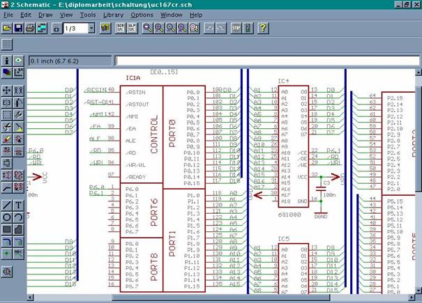
Fig 6: Development
Environment for the hardware development; EAGLE Layout Editor
The
programming of the microcontroller C166 was done with the development �Vision
of the company Keil
One finds
in �Vision, Version 2 the basic elements of a modern IDE:
�
A specially adapted text editor.
�
An ANSI-C-compiler (C166-ANSI-C-compiler),
�
A Assembler
(A166-Assembler),
�
A left/Lokator (L166),
�
A debugger ( �Vision2
Debugger)
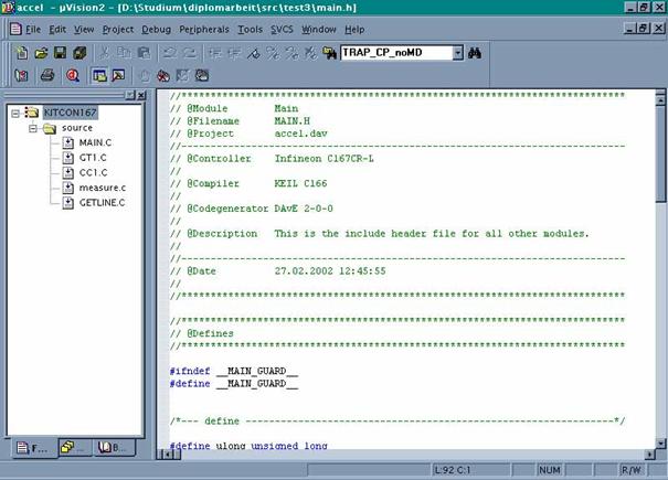
Fig 7: Development
Environment for the software development; �Vision2 Text Editor
In this
chapter will be the implementation of the Advanced Inertial Measurement System
explains. After the block diagram of the Me�datenaufnahme Me�datenaufnahme is
the shifting of the presented, the individual parts of the circuit are
described in detail, on the same principle will be the implementation of the
described Me�datenaufbereitung and, in the case of the Me�datenaufbereitung
even the description of the developed software on the Microcontroller is added.
The task
of the Me�datenaufnahme consists in, and the movement of the airship and the
earth's magnetic field to capture the Me�datenaufnahme is composed of three
acceleration sensors, three roundabouts and three magnet sensors together.
Figure 8: Block diagram of
the Me�datenaufnahme
For the
adaptation of the Sensorensignale Me�datenaufbereitung to the additional
Signalanpassungsschaltungen be required.
The whole
circuit for the Me�datenaufnahme is shown in Annex A, the following are the
individual areas of the circuit described in more detail.
Accelerometers
measure, as the name already says, the rate of change of velocity, by creating
electronic signals, the measured or to control a process can be used, and
traditional applications include the activation mechanisms of safety belts and
air bags, in which the sudden deceleration of the accelerometer which is
responsible for the security techniques in gear sets.
The above
sensors use a mechanism, the with of the elongation of a spring can be
compared, the force, by the acceleration due to is, extends the spring, with a
higher acceleration is even more stretched the spring. The measurement of the
Deformationslangen and the acceleration can be determined.
Figure 9: Block diagram of the Beschleunigungsaufnahme
The
ADXL210 is a "low cost" 2Achs-Beschleunigungssensor with low power
consumption, and the measurement is between - 10g and +10G. The special on the
ADXL210 are the digital outputs on the two axles, the outputs are digital
signals, whose length (ratio of the pulse width to the period) proportional to
the acceleration in two axles are. These outputs can directly be measured with
a Mikrocontroller-Zahler. There is no ad-converter needs. The
Arbeitszyklusmodulator (DCM) has a resolution of 14 bits, based on this special
properties, the acceleration with a simple schema record. After Fig. 9 , the digital outputs of the
sensor to the microcontroller directly connect the circuit for the embedding of
such an accelerometer is in the figure 10 shown.
The
ADXL210 is to configure the following: the length of the period and the
bandwidth of the signal output (e.g. , elimination of high-frequency
vibrations). These settings are described below.
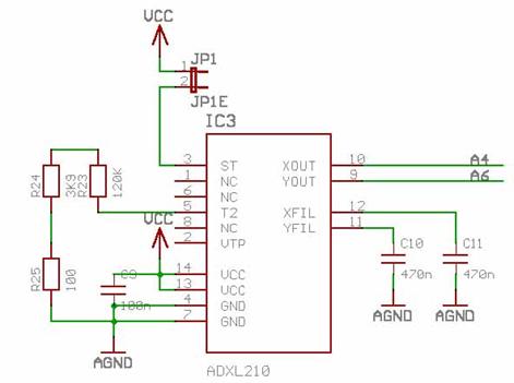
Fig 10: Embedding an accelerometer
The error behaviour of the acceleration sensor
The
sensor failure da of the ADXL210 is in general from a scale factor error k, a bias B and a stochastic noise process w , so that the error can be described as follows:

There is a
possibility, before each experiment to determine the bias, so can the error
with a much lower bias be assessed, as without this information.
The
ADXL210 from Analog Device is
set to 100 Hz bandwidth. This setting is By Cx and Cy (here C10 and C11 connector, see 10), determines, two capacities are to pin 11
(Yfilt) and 12 (Xfilt) connected, and the calculation of the capacity is as
follows:
 ���������������������������������������������������������������������������������������������������������������������������� (
51‑ )
���������������������������������������������������������������������������������������������������������������������������� (
51‑ )
 ������������������������������������������������������������������������������������������������������������������������������������ (
52‑ )
������������������������������������������������������������������������������������������������������������������������������������ (
52‑ )
|
Bandwidth
|
Capacity
|
|
10 Hz
|
0.47 mF
|
|
50 Hz
|
0.10 mF
|
|
100 Hz
|
0.05 mF
|
|
200 Hz
|
0.027 mF
|
|
500 Hz
|
0.01 mF
|
|
5 Khz
|
0.001 mF
|
Table 1: Bandwidth
The
length of the period at the sensor output is determined by a resistance Rset (in the image R23+R24+R25), is
connected with the GND, the equation is then:
 ������������������������������������������������������������������������������������������������������������������������������������ (
53‑ )
������������������������������������������������������������������������������������������������������������������������������������ (
53‑ )
|
T2
|
Rset
|
|
1 MS
|
125 KW
|
|
2 MS
|
250 KW
|
|
5 MS
|
625 KW
|
|
10 MS
|
1.25 MW
|
Table 2:
Resistance values for the setting of the period
The angular
velocity with a roundabout you can be record. This recording is in the Fig. 11 shown to adapt it to the
microcontroller a Butterworth filter be added and an amplifier.
Fig 11: Block diagram of the Winkelgeschwindigkeitsaufnahme
The
"heart" of the gyroscope is a Keramikstab, which, in its longitudinal
axis is brought to vibrate, the rod is in two places with Metallgabeln welded
to the "nodal point" of the rod are, and when the rod to rotate is
placed on the vertical plane to a vibration appears through influence, the with
the angular velocity is the same, the on the rod mounted piezo-electric plates
are both a way to swing the rod longitudinal to bring, as well as the vibration
generated by the appears through influence on the vertical plane should be
repealed, and the voltage, the repealing of the vibrations on the vertical
level is necessary, there is information on how fast the rod (and therefore,
the gyroscope) is turning. The gyroscope in this way creates an output voltage
that is proportional to the angular velocity is.
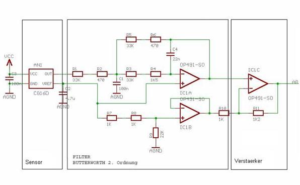
Fig 12: circuit for the
Winkelgeschwindigkeitsaufnahme
The output
of the Kreisel-Sensors is an analog voltage to Noise-Reduzierung and the
antialiasing is the sensor a Butterworth filter 2. Ok downstream and the
resulting signal is output through a 1.2 -fold at the amplifier AD-converter
led of the microcontroller, you used to strengthen a IC of analog device of the type OP491.
The
Butterworth filter is used only resistors and capacitors with fault tolerance
of 1 %. This is necessary, because of the filter must be exactly in the
calculation of the resistors and capacitors are C1 with 22 nF and C2 with
100nF commanded. Based on these values can then the values of the other
resistors be determined.
 ������������������������������������������������������������������������������������������������������������������������������������������������������������ (
54‑ )
������������������������������������������������������������������������������������������������������������������������������������������������������������ (
54‑ )
 �������������������������������������������������������������������������������������������������������������������� (
55‑ )
�������������������������������������������������������������������������������������������������������������������� (
55‑ )
 ������������������������������������������������������������������������������������������������������������������������������������������� (
56)‑
������������������������������������������������������������������������������������������������������������������������������������������� (
56)‑
 The
following constants are specified:
The
following constants are specified:
A0 = 1; a1 = 1.4142 ; b1 =
1
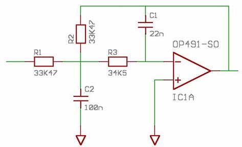
Fig 13: Butterworth
As a
fixed values has been C1 with
22 nF and C2 set with 100
nF. It follows after the forming of equation ���� (
56):‑
 �������������������������������������������������������������������������������������������� (
57‑ )
�������������������������������������������������������������������������������������������� (
57‑ )

As a last
then you can R3 calculate
 ���������������������������������������������������������������������������������������������������������������������������������� (
58‑ )
���������������������������������������������������������������������������������������������������������������������������������� (
58‑ )

The current
direction of the airship can be seen, in which you have a sensor that the
magnetic field on the surface of the earth measures, uses, this compass is in
the figure 14 briefly presented. With a instrumentation
amplifier is the output signal from the sensor connected to the
microcontroller.
Fig 14: Block diagram
of the heading indicator
Magnetoresistic
sensors from Honeywell are simple bridge connections (Figure 15), the only an
input voltage need to to measure magnetic fields, and if a voltage from 0 to 10
volts to Vbridge is connected, begins to the sensor, a magnetic fields to
measure in the environment. In addition, the sensor two "on chip
straps", the offset and the Enter reset switch.
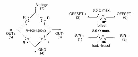
Fig 15: on-chip component
of the Kompa�sensors
The
offset-bridge can be different operating modes, if a DC by the offset-bridge
flows. An unwanted, but known magnetic field can be subtracted out.
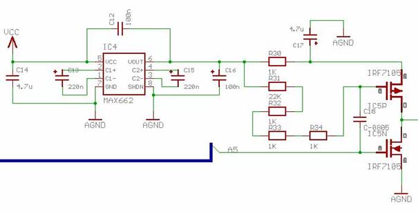
Fig 16: Set/reset
circuit for the Kompa�sensor
The Set/reset
(S/R) can be a high current pulses, which are then very useful, if the sensor
in a highly sensitive work mode can be, and most magnetic sensors, measure the
low field strengths, are influenced by larger magnetic fields (> 4 - 20
gauss), the can lead to a Ausgangssignalverminderung. In order to to reduce
this effect, and to the signal at the output to maximize, can a magnetic
circuitry (Fig 16) on the S/R will be applied, the eliminated the effect, with
the help of IRF7105 brings top is at the exit of the Set/reset circuit with a
power output of approximately 3A present, the purpose of Set/reset (S/R) is
more sensitive to the sensor back to make small field strengths. This is
accomplished, by a large current through the S/R pulsates.
The analog
output signals of the sensors require a reference voltage, this reference
voltage is the building block by UM780 AD generated, as both
Referenzspannungerzeuger, as well as use Temperaturanderungssensor. By AD780 is
a Ultrahochprazision "Bandgap" generated reference voltage, the 2.5 V
or 3.0 V provides. The required input voltage can be between 4-36 volts.
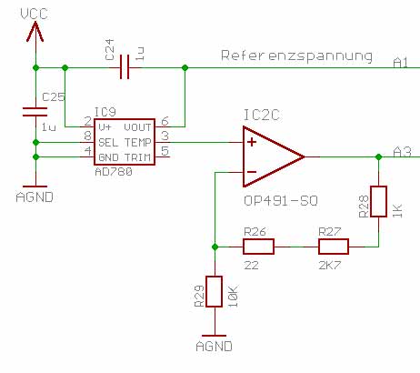
Fig 17: Reference
Voltage
In addition
to the reference voltage generated of the AD780 is still a further output
voltage, the correlated with the temperature difference (in fig 17This is the output (A3), A3 provides a voltage, is dependent on the
linear of temperature fluctuations, it is intended to help the non-linearity of
the sensors to correct with the help of the data sheets and data collected.
A room
temperature of 25 C is the outlet temperature voltage of 560 mV (according
to the data sheet) with a "temperature sensitivity" of 1.9 mV/�C,
since the reference voltage of 2.5 volts and AD-converter of the
microcontroller a resolution of 10 Bit has, the system has a resolution of:
 .
.
To the
capture of signals to simplify, was elected an amplifier of 2.47 (see Figure 17), that are each temperature changes ensures that you can be covered, a
+ 1 C temperature change
then caused a change in voltage at the output of + 4.7 mV. during the room
temperature is the output voltage: 1.48 V.
The three a
wide array (acceleration sensors - Drehwinkelmessung and telemetry,
magneticfield measurement, etc.) each have three components (each for the
measurement in the x-, Y-and z-direction). In all three Sensorpaketen the
sensors must be (responsible for the Me�datenaufnahme) also in the direction of
the corresponding spatial axs (X, Y, and z-axis) be aligned, i.e. , that a
package two sensors (e.g. , for the Me�datenaufnahme in x and y-direction) in a
plane, and the third sensor ( e.g. for the Me�datenaufnahme in Z-direction) in
a vertical plane.
This can be
realized by two sensors each of the three a wide array on a circuit board and
the third sensor placed all three a wide array on a second board, perpendicular
to the first circuit board is mounted.
Fig 18:
Komponentenbesetzung on the circuit board 1 and 2

Fig 19: Platinenansicht
of IMU-overall system
Fig 20: Block diagram of the Me�datenaufbereitung
(Sensordatenaufbereitung)
The
Me�datenaufbereitung is with a microcontroller (with additional memory and
peripheral components) are realized.
The shift,
the the microcontroller with the additionally required memory and peripheral
components connects, is listed in Appendix B, the following are the individual
sections of the circuit described in more detail.
Supply voltage
is used as a component of the type 78M05. In the component is an input voltage
between 7.5 volts and 12 volts input. As a output voltage is 5 volts, all
components work with 5 volts of power. The pins of the inputs are via the
jumpers JP2 and JP6 (see Figure 23). A LED can the jumper JP7 to be connected, the lit LED indicates that
the supply voltage is working properly.
For the
reference voltage there are two possibilities: either the supply voltage of 5
Volt be used as a reference voltage, or it can be connected a separate
reference voltage, which can be selected by jumper settings (see JP10 in JP11
in the table 3).
If you feed a own reference voltage, which will not exceed 5 volts, there is no
22 Pin of connector SV2 is available (see table 9 ).
The
microcontroller is to 256 KByte ROM (2 blocks per 128 Kbytes) and 256 KByte RAM
equipped. The used Rome is of the type 681000, the RAM of the type 29F010 of
the Philips company, with the power supply of RAM was a second supply voltage
available to potential losses to avoid the memory, and the building block
MAX690 machines only (by Maxim) takes on this task (see Figure 21). The output Vout of the module MAX690 machines only there is a
constant output voltage from. As soon as VCC is less than 5 volts, the building
block to battery power, this will allow the data from the RAM, a data loss by
shutdown or weakening of the input voltage is avoided, however.
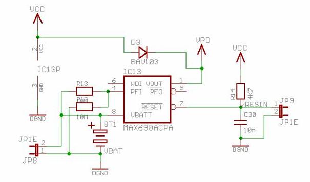
Fig 21: circuit for the
Eingangsspannungsuberwachung
For a
connection with other computers or for the programming of the flash RAM, a
serial interface and a CAN-bus to the board appropriate. Instead of a port a
CAN-bus the connection can also used as a second serial interface be. The first
interface X1 (see Figure 22) is the first serial port interface X2 can be either as a CAN-interface
or as a second serial interface operated. The switchover is by JP3 and JP4.
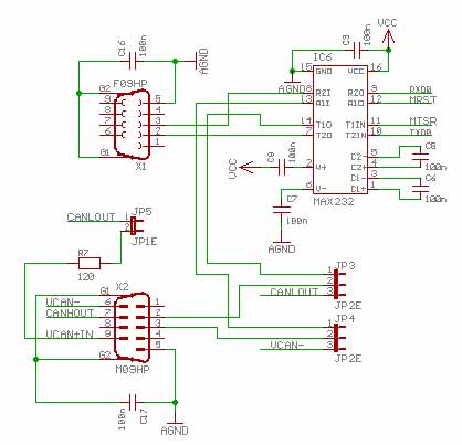
Fig 22: serial
interface will be started
The
microcontroller board can be configured with different jumper settings, and
there is still an additional switch to the RAM or the Rome to configure.
The
jumper settings have the following functions:
|
|
Default Setting
|
Alternative setting
|
|
JP1
|
(1 +2)
|
CAN-VCC
generated by Supplay
|
(2 +3)
|
CAN-VCC
generated by CAN-network via DB9-X2
|
|
JP8
JP9
|
(2 +3)
|
DB9-X2
works as CAN
|
(1 +2)
|
DB9-X2
works as a second serial specific
|
|
JP10
|
(1 +2)
|
VAREF generated by VCC
|
(2 +3)
|
VAREF
generated by external Suplay on SV2
|
|
JP11
|
(1 +2)
|
RGND generated by DGND
|
(2 +3)
|
RGND generated by external earth via SV2
|
Table 3: jumper settings
on the microcontroller board
As for
the components of the Me�datenaufbereitung no special spatial directions (as in
the Me�datenaufnahme) are required, the entire Me�datenaufbereitung on a
sufficiently large board will be realized.
It shows
that the whole circuit for the Me�datenaufbereitung on a four-layered
EURO-board is to realize.
The first
of the four layers is the Bestuckunsseite, an interlayer is the ground, a
second intermediate layer is connected to the supply voltage, and the fourth
layer is used as a solder.
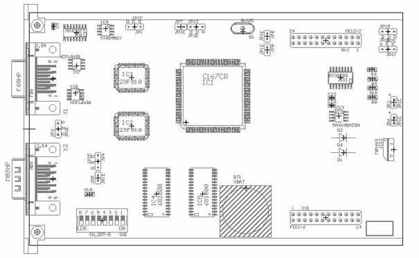
Fig 23: component side
of the Mikrocontrollerboards
Fig 24: solder side of
the Mikrocontrollerboards
The
actual Me�datenaufbereitung is realized by a software on the microcontroller
(C167) expires.
Signals
from sensors are recorded and edited, depending on the switch settings will be
different operating modes, and forwarded to multiple LEDs (i.e. , the LEDs show
the current mode). The edited data is then given to the serial interface.

Fig 25: Environment of
the microcontroller
Figure 26: state diagram
for the Me�datenaufbereitungs-Software
CALIBRATION
In this
condition, the initialized and/or calibrated sensors. In the acceleration
sensors is the period on the DCM-output measured. The IMU must once again to
the x-, Y-, and z-axis will be rotated, this will determine the force of
gravity, the later in the Gravitationskompensation is used.
The
system can be moved in the Calibration-Zustand, by the START_
Calibration-Befehl there is, after turn of the IMU can then this state with a
stop Calibration-Befehl be terminated after calibration, the system in the
READY_MEASURE-condition.
READY_MEASURE
This
condition is considered a transition state, it will be no data from the sensors
detects. This operating mode is used only for the preparation of the next
status. With the command START_MEASURE the system goes to the next state.
The
condition READY_MEASURE can only be achieved if the system has already been
calibrated, which means that the condition is never reached, if the system has
not yet been calibrated, which makes it the faulty measurement of the sensors
prevent another transition in the calibration state calibration is possible,
however, in the man the Start_calibratoin-command is there.
Measure
In this
condition in certain periodic cycles, is the data collected by the sensors,
after error correction, and calculations (Me�datenaufbereitung) are the data
obtained on the serial interface given. This you get the current measured data
on the serial interface.
The
program processes the data from the sensors and then you are to the serial
interface, the user can use serial interface defined commands to the
microcontroller to the program of a condition to put in the other (see Fig 26).
You can
also reach a transition of the program, in which various switch, the with pins
of the microcontroller are connected, actuated. Whether the command over the
serial interface or the of a switch has a higher priority, can be set a
separate switch, should be in the General commands via the serial interface
have priority.
The
processes of the system are in the following SA-graph (circles mean functions
or processes, arrows mean data flows):
The user
interface is used for the test case for this purpose, to communicate with the
microcontroller, so between the different modes can be switched.
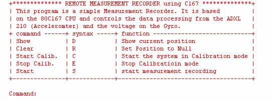
Fig 27: User Interface
of the IMU for testing purposes.
The user
has the option, the system with five different commands to affect:
Show
The
formula s= 1/2 a t� the user receives in the primitive test case the current
position in relation to a starting position, in which the Board at the start of
the program was. This command can only be executed when the system is already
calibrated and has been started.
Clear
Sets all
readings back to zero, so a new measurement can be started, if you have already
been calibrated.
Start calib.
The
system is brought into the calibration mode, the sensors must now by hand to
the rotary axs (X-, Y-, and Z-axis) be rotated once.
Stop calib.
Let the
program go to a condition when loaded and ready to launch.
Start
Starts
the Measurements
In the
collection of the accelerometer data a special procedure is necessary.
Roundabout,
Kompa�sensoren and temperature and/or reference voltage are on to the
AD-converter of microcontroller connected, and the data that will be without a
special routine converted into a digital form.
The
outputs of the acceleration sensors
are in the form of digital signals before. This is used for decoding a special routine
necessary.
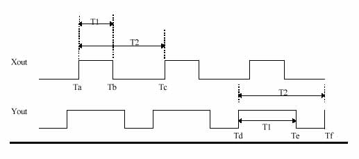
Fig 28: Sensor Output
of ADXL210
To the
two components of a accelerometer to determine, you need to have the
Signallangen of T1 and T2 of the two outputs of the sensor
(see Figure 28).
A counter will be with the rising edge of the x-output (Ta = 0) started. The count on the signal
covered (TB) is stored during running timer, the contents of Timer is on the
following rising edge of the x-output (TC) is stored and, at the same time
stopped, a process which will then for the Y-output repeatedly (TD,
TE and Tf).
T1 and T2
are then easily calculated with the following formulas.
 ��������������������������������������������������������������������������������������������������������������������������������������� ( 59‑ )
 �������������������������������������������������������������������������������������������������������������������������������������� ( 510‑ )
In normal
use, if no high accuracy is required, you can the acceleration with the
following simple Naherungs-Formel calculate (see [ 4] ):
 ����������������������������������������������������������������������������������������������� ( 511‑ )
With the
given "low cost" sensors can be a high level of accuracy only
achieved by a suitable software will be in accordance with the data sheet of
ADXL210 is to achieve a higher level of accuracy, the following routine to use
in the process (see [ 4] ):
At the
beginning the system should be placed in the Kalibrier-Zustand, and then with
each component of the Beschleunigungs-Sensors be made the following:
The
Komponenten-Richtung lies horizontally, then slowly to the sensor is full
360o rotated, and in such a way that the Komponenten-Richtung the zenith
(direction that is perpendicular to the top) cuts. If the Komponenten-Richtung
in the Zenit shows, should measure the accelerometer -1g, according to +1g, if
the Komponenten-Richtung vertically downwards.
Meaning
of the variables in the following formulas:
|
T2cal
|
|
The
value of T2 during the calibration.
|
|
Zcal
|
|
The 0 g
of T1 during the calibration.
|
|
Bit
scale factor
|
|
Bitnormierungsfaktor
|
|
K
|
|
Scale Factor
|
|
|
|
|
 ������������������������������������������������������������������������������������������������������������������������������� ( 512‑ )
 ����������������������������������������������������������������������������������������������������������� ( 513‑ )
The
current acceleration can be calculated as follows:
 �������������������������������������������������������������������������������������� ( 514‑ )
Where:
 ����������������������������������������������������������������������������������������������������������������������������� ( 515‑ )
In this
chapter are test results of tests of the IMU-presented overall system, and the
first thing will be results of the tests described, then
Mikrocontroller-Programm tests to be described.
After all
boards were manufactured, some of the tests were carried out before the system
was put into operation, in this test is the measurement of the output voltages
of Gyros and to measurement of DCM-signals that are produced by the acceleration
sensors.
An input
voltage of 5 volts to the circuit board is connected, the voltages on Gyros and
other components are measured with the voltmeter, while in the acceleration
sensors the Signallangen be displayed with the oscilloscope.
In
general, this test, the function of each of the components tested so you can
determine whether the sensors are working or not.
|
Test Description
|
Result
|
Large
|
|
Roundabout No1
|
2.4
|
Volts
|
|
Roundabout No2
|
2.4
|
Volts
|
|
Roundabout No3
|
2.3
|
Volts
|
Table 4: Results of the gyros
6.7 Test of the overall system with the
microcontroller (C167)
After the
successful Hardware-Test was the collection of data by using the
microcontroller (C167) tested the company PHYTEC. This is not the developed in
the present work microcontroller board, but a testboard contains of Phytec.
This evaluation module has been with the developed in the present work
connected sensor boards.
In the
test were the Signallangen every 100 ms (see Fig 28) of the Beschleunigungskomponenten senses, there were 100 stored values
were then output through the serial interface and displayed.
The IMU
rested this series (i.e. , no movement has been run).

Fig 29:
the accelerometer, in X-direction
Fig 30:
the accelerometer, in Y-direction
Fig 31:
the accelerometer, in Z-direction
Although
the sensors are not moving, were the data collected did not constant, the
deviations to the constant value are + 1 counters (i.e. ,
about 0.1 % ). This is located on the timer of the microcontroller while the
clocking.
In this
attempt, the above error measured by averaging the data be reduced:
The
period T1 takes 1ms in test1 was sampled every 100 ms, i.e. each hundredth
value of the sensor has been detected in test2 are now all 100ms the first ten
values (in the distance of 1ms) detects and of these ten of the mean value is
formed, this average is now considered the (every 100 ms) sampled value.
Fig 32:
the accelerometer, in X-direction
Here the
data of the roundabout in a similar manner, it showed that coverage without
averaging (according to Gesamtsystem-Test 1 for the acceleration sensors) the
values of the dormant roundabout more of a constant value which differed
(approximately 0.5 % ). A averaging was not made.
Fig 33:
the accelerometer, in Y-direction

Fig 34:
the accelerometer, in Z-direction
It was a
partly functional IMU finished, with only the microcontroller to
Me�wertaufbereitung must still be tested for functionality, and the first
results of the tests are described in the Chapter 6 under this test is simple
tests in dormant sensors, it is not yet to the Error Correction him part of a
temperature change of the sensors, the Kompa�sensoren have not yet been tested,
because the time was in very short.
The
Mikrocontrollerboard could not be tested because some problems occurred during
the commissioning of the microcontroller, these issues have been corrected, but
it could not be carried out more software testing.
In
order to assess the system as a whole, had to be made many more test, with
ongoing uptime would, however the differences especially in the roundabouts
accumulate, but it became so in regular, not again to large intervals an
updated, with the correct reference value (for example, through a GPS-system)
the IMU offsets, i.e. , the next step would be the further development to a
hybrid system.
Literature
�[1]
BROCKHAUS, Rudolf: "Flugregelung"; Springer Verlag; Heidelberg u.a.
1994
[2] DOROBANTU, Raul: "Simulation des
Verhaltens einer low-cost Strapdown IMU unter Laborbedingungen";
Technische Universitن
t
M�nchen; M�nchen.
[3] MOSER, Luethi/ MOSER, Thomas: "Low Cost
Inertial Navigation System"; Electronic Laboratory of Swiss Federal
Institute of Technology, Zurich. 2000
[4] WEINBERG, Harvey: �Using The ADXL202 Duty Cycle Output�; NORWOOD, MASSACHUSETTS.
[5] �Low Cost + 2g/+ 10g Dual
Axis Accelerometers with Digital Output�; NORWOOD, MASSACHUSETTS
[6] CARUSO, Michael J: �Applications of
Magnetoresistive Sensors in Navigation Systems�; Honeywell Inc
Inhaltsverzeichnisi.............................................................................................................................
Abbildungsverzeichnisiii..................................................................................................................
1Introduction1..................................................................................................................................... �����
The Solarluftschiff Lotte1 1.1
.""...........................................................................
1.2Task2���� ............................................................................................................
1.3 Mega Pixels Overview2..................................................................................
2Basics4............................................................................................................................................... �����
2.1Real-time systems4...........................................................................................
Border Cooperation � 2.2Hardware4..................................................................
2.2 .1components and classifications4....................................................... ......................
2.2 .2The microcontroller family C1666 -.................................................. ......................
2.2 .3The C167 microcontroller family7..................................................... ......................
2.2 .4The memory organization of the C1679 tool.................................... ......................
2.2 .5The interrupt system for the C16711................................................ ......................
2.2 .6The Timereinheiten14........................................................................ ......................
2.2 .7Capture Compare Unit (Capcom)15................................................ ......................
2.2 .8The Pulsweiten-Einheit
PWM16........................................................ ......................
2.2 .9Analog Digital
Converter (ADC)18.................................................. ......................
2.3Control of servo motors 20..............................................................................
3Architecture
Design of the Aktorik-Ansteuerungseinheit (engl, Actuator Control Unit (ACU)22��������� ....................................................................................................................................................
Version 3.1
voltage regulation22..........................................................................
Really
3.2Betriebsspannungsuberwachung23.....................................................
3.3 Basisbetriebszustands-Einstellung
23.............................................................
3.4
Steuersignal-Erzeugung 24.............................................................................
Another
3.5Notsteuerungsbaugruppe25.............................................................
Pinhole 3.6operating states of the
ACU26...........................................................
3.7Modularity of the ACU26................................................................................
4Development
Environment29)........................................................................................................ �����
4.1
Hardware-Entwicklungsumgebung 29.........................................................
4.2 Software
Development Environment 30.......................................................
5Realisation of the ACU31................................................................................................................ �����
5.1
Versorgungsspannungs-Stabilisierung 31......................................................
5.1 .1circuit design for the
Versorgungsspannungs-Stabilisierung 32..... ......................
5.2Waiting
Betriebsspannungsuberwachung34..................................................
5.3
Basisbetriebszustands-Einstellung 36.............................................................
5.3 .1circuit design for the
Basisbetriebszustands-Einstellung 38............. ......................
5.4
Steuersignal-Erzeugung 40.............................................................................
5.4 .1The hardware of the Steuersignal-Erzeugung 42............................. ......................
5.4 .2The
monitoring and the forwarding of the PWM-signals from the remote control
(normal B)42 .........................................................................................................
5.4 .3 Notsteuersignal-Erzeugung stage 149............................................. ......................
International
5.5Notsteuerungsbaugruppe51.....................................................
5.5 .1circuit
design for the monitoring of the control signals on the output of the ACU and
the channel5-output of the Fernsteuerempfangers51.......................................... ......................
5.5 .2circuit
design for the Notsteuerungsbaugruppe52........................... ......................
5.5 .3circuit
design for the forwarding of the PWM signals from Fernsteuerungsempfanger (
Luftschiff-Startphasen -Operation)53............................................................. ......................
5.6Layout
design of board 1 ( "Voltage regulation", "
Basisbetriebszustands-Einstellung " and " Notsteuerungs-Baugruppe
" )54..........................................................................................
& 5.7the boards.................................................................... of the ACU55
6Experimental
results56.................................................................................................................... �����
Construction of the 6.1�'
authorisation Testplatzes56.......................................
6.2Experiments and test57..............................................................................
6.3The ordered test57.......................................................................................
6.3 .1Test articles
159.................................................................................. ......................
6.3 .2Test 260............................................................................................... ......................
6.3 .3Test 361............................................................................................... ......................
6.3 .4Test 461............................................................................................... ......................
6.3 .5Test 562 New...................................................................................... ......................
7Summary and
outlook64.................................................................................................................. �����
Literature65
rating..............................................................................................................................
Appendix A66
motorway................................................................................................................... �����
ANNEX B69........................................................................................................................................ �����
Figure 1:
An airship2�
2: Overview of different processor families5�
3: Block diagram of the C167he family8�
4: Memory organization of the C1679
tool
5: Layout of a Interrupt Control
register of the C16712�
6: The building of a Timer-Einheit 14�
Fig 7: Timer T015 hand brake�
Fig 8: Control register PWMCON017�
Fig 9: Control register PWMCON017�
Fig 10: The ADC circuit diagram19�
Figure 11: shows the Servo in 3
different states21�
Fig 12: The architecture of the
actuator control Unit (ACU) of the "alternative Lotte"22�
Fig 13: States and their transitions of
the ACU. remarks, see sections 3.1 to 3,526�
Fig 14: architecture of the ACU
(detailed description)28�
Figure 15: development environment for
the hardware development; EAGLE Layout Editor 29�
Figure 16: development environment for
the software development; �Vision2 Text Editor30�
17: Block diagram for the "
Versorgungsspannungs-Stabilisierung '31�
Fig 18: circuit "
Versorgungsspannungs-Stabilisierung '32�
19: The block diagram for
Betriebsspannunguberwachung34�
Figure 20: for the
Betriebsspanunnungsuberwachung Programmablaufplan on the �C35�
Figure 21: Block Diagram "
Basisbetriebszustands-Einstellung " with Environment36�
Figure 22: state diagram for the
manifold of the " Basisbetriebszustands-Einstellung " (see fig.13 in
section 3.6 above ) "37�
Figure 23: Part 1 of the switch between
Luftschiff-Startphasen -operation and normal operation (LSB/NB-switch, part1)38�
Fig 24: Part 2 of the switch between
Luftschiff-Startphasen -operation and normal operation (LSB/NB-switch, part2)38�
Fig 25: Block diagram of the "
Steuersignal-Erzeugung '. 41�
Fig 26: finite state machine for the
" Steuersignal-Erzeugung ". (See Figure 13 in section 3.6 above )42�
Fig 27: for the Aktorik-Ansteuerungsprogramm
Programmablaufplan on the �C43�
28: Capture mode45�
Fig 29: T0 and CC1 in Capture mode47�
Fig 30: PWM-production in the Mode PMX
= 050�
Fig 31: for the Blockdiagram
Notsteuerungsbaugruppe51�
Fig 32: Monitoring of the control
signals (PWM signals) at the output (CAKTIV) of the ACU and the channel5-output
of the Fernsteuerempfangers (P2.5)51m�
Figure 33: Notsteuerungsignal-Erzeugung
- level 252�
Figure 34: One of the three generated
PWM signals, which is created through the combination of the clocks of the two
expands flip-flops (explanation, see text)53�
Figure 35: the layout design of printed
circuit board 154�
Fig 36: the two boards (1 and
2) The ACU55�
Figure 37: the receiver and the
actuators (engine,servos) are on board 1 angeschlossen.55�
Figure 38: Testplatzaufbau56�
Fig 39:59 PM���
Fig 40: Test 260�
Figure 41: Test 361�
Fig 42: Test 4, CH1 = channel 5; CH2 =
input signal from channel 4; CH3 = output from the microcontroller; CH4 =
output channel 4 of the ACU62)
Figure 43: Test 5-1, CH1 = channel 5;
CH2 = input signal from channel 4; CH3 = output from the microcontroller; CH4 =
output channel 4 of the ACU63)
Figure 44: Test 5-2, CH1 = channel 5;
CH2 = input signal from channel 4; CH3 = output from the microcontroller;
CH4 = output channel 4 of the ACU63)
List of Tables
Table 1: Overview of the C166 microcontroller
family7�
Table
2: interrupt resources of the C167)
(Part 1)12�
Table 3: summarizes the inputs and outputs
of the LSB/NB-switch together:39�
Table
4: shows the channel no.., and the corresponding connections and
Capture-Register 44�
Table 5: shows the DCLS Einheit-Ausgange and
their corresponding timer49 (
Airships in the last years experience a renaissance, and
at the University
of Stuttgart was a
Solarluftschiff (Lotte) has been established, the Institute for statics and
dynamics of the air and Raumfahrtkonstruktion has in February 1992 the project
"Solarluftboot" has started. objective was to use new materials and
construction, to achieve a solar and new concepts of the steering, and
navigation scheme to implement.
At the Institute for as aeroelasticity, flight mechanics
and control engineering (IFR) is in this context with the methods of
identification, as a model is only formed from measuring data, without physical
knowledge of the object to be involved, for this procedure you need accurate
data on the movement of the object to tailored to the IFR is a measurement and
navigation structure, with the trajectory and the location of Lotte is captured
and recorded.
One of
the airships is replaced by the means a loss of gas its buoyancy, today usually
incombustible Helium, formerly it was hydrogen, and the means a loss of gas
because of its low density is "easier "than air and therefore
generates a boost, a cubic meters of helium is about the capacity of a
kilogram, you therefore requires a lot of volume, in order to to take a lot of
weight, therefore, airships voluminous body, and the load-bearing capacity is
increased with the 3 power of the long, it's perfect for this would be the
shape of a ball, but as you but as much as possible with a large speed and
small driver want to travel, is a form with a smaller resistance sought, from
which the elongated fish or cigar will see figure 1, but the shape was like
driftwood in the water in the air and bustle, if not lead plants were
attached to the stabilization, which will be fitted with oars, which, as the
ship or plane distract the flow to the change in direction and thus the
controllability manufacture so you have three essential conditions: the impetus
for a voluminous body as much as possible, minimiye the airodyamic resistance due
to a streamlined form, carefully calculated to as much as possible the main
plants and rowing.
Figure 1:
An airship
For the
above mentioned Solarluftschiff Lotte is the University
of Stuttgart with the support of the University of Karlsruhe an alternative flight control
system (flight control system - FCS) developed, which takes into account modern
information technology methods.
In
the present work is to Aktrorik-Ansteuerung and their connection to the
alternative FCS will be developed.
The goal
of the national work it is, a Aktorikansteuerungs-Baugruppe (AABG) for the
flight control system (FCS) of the airship "alternative Lotte"
to realize.
First,
the basics regarding real-time systems and embedded systems presented.
Then, the
architectural design of the AABG presented.
Afterwards,
the realization of the described parts, and that the draft board was carried
out with the program package EAGLE. In the implementation of the Software
(Microcontrollerprogramming) has been the program Vision ver, wedge used 2.03
& of the company, it is a shareware version for a limited code size of
16 Kbytes, the programming language is C.m
Thereafter
some test results of tests of the entire AABG presented.
The
content of this chapter is [ 1], [ 2], [ 3] and [ 4] issued.
For
systems that are of a mechanical, electrical and data processing part, it is of
crucial importance that the information processing happens so quickly, as the
mechanical part of or the entire system needs, such as a plane sensors and
actuators, and there are information technology units that the sensor data
processing, and, according to the actuators of an implemented control loop, and
it is the information processing in all your components be at least as quickly,
that the actuators (Helm, etc. ) get their commands in time, so that the
planned rail can be flown.
This circumstance of the timeliness is called
real-time, and the real-time capability of a system, or a component ensures the
processing of a task within a defined time frame, and this can occur in the
case of a network the guaranteed delivery of information or in the case of a
operating system is the answer of a task to certain aktionsauslosende events
within the defined maximum latency be.
������������������������
The rapid technological progress causes that is nowadays
an unmanageable size variety of components available on the free market is, in
figure 2 is an example of a very broad
overview of a small part of available given Mikroprozessorfamilien. The
classification in the discretion is based on experience and have been made to
be regarded rather as a grows.
Figure 2: Overview of different processor
families
For the engineer in this context is often a problem of
the selection and selection of an appropriate product for the task, we need to
solve, for this is it I. A, necessary, and the individual products
according to classify, classify and to be able to assess, and in many cases the
task is mostly more difficult by the fact that many of the products of various
categories merge with each other, do try to classify you different products or
to compare, so you should always the target application to the fore, and try
for this to find the best solution, a simple comparison with Benchmarks makes
no sense, if you don't for a concrete example of the application into
consideration investigated you, for example, microprocessors, these can be
roughly classified according to their data bus width (16 bit, 32 Bit, ... ),
your scope (controller, signal processor, pure microprocessor, ... ) or even
after the scope of your instruction set
(RISC, CISC, ... ) and of the underlying architecture,
and a further, incomplete
List of criteria to be taken into consideration is the
following:
�
Price/piece
�
Pieces, availability, compatibility
�
Space, available
housing types, required peripherals, etc.
�
Power consumption (power
supply, heat dissipation, ... )
�
Development environments
(programming languages, simulators, emulators, .... )
�
Maintainability, modularity, integrity, etc.
All of these decision-making criteria are on a
case-by-case basis according to be weighed and new to weights.
The C166he family was from the company Infineon
(formerly Siemens) in the first line for time-critical control, and control
tasks developed, equipped with a 16-bit wide data bus and numerous peripheral
devices provides it to the user a very powerful, integrated solution is
available, as typical for a controller it has a distinct Interrupt-System ,
many configurable I/O lines and various timer, in table 1 is an overview of the various families of the
C166he given microcontroller, as is seen, are very many Members of this
controller family in addition with integrated analog Digital Converters (ADC),
capture Compare units, a PWM module (PWM) and serial interfaces.
Table 1: Overview of the C166
microcontroller family
This 16-bit microcontroller family comes with only a
very small number of machine instructions of the C166 has for example, only 78
asm statement, in most cases only a single machine cycle to be processed, due
to the very low number of commands that the controllers can than RISC
type be classified with some extensions.
The memory organization is in a von Neumann architecture , i.e. ,
programs and data-sharing is a linear address space together, and each
peripheral components, however, are quite modular and with a very complex
networked bus system, which allows the parallel execution of internal transfers
between the modules and the calculator.
The C167he family is based on the architecture of the
C166 family, the to 1990 by the Siemens company was newly developed in Munich, in contrast with
other microcontrollers and microprocessors was in a more modern, newer concept.
The focus has been on a more efficient interrupt treatment, the optimized
ability, with individual bits to work quickly and efficiently, and to increased
throughput between the on-chip peripherals, the memory and the CPU, put. In
addition, played the expandability with other peripheral modules, a important
role, in order to for various applications to obtain an optimized
microcontrollers, Figure 3 shows the
internal block structures of the C167he family and gives an overview of how the
individual modules are linked together.
Figure 3: Block diagram of the C167he
Family
The most important structural elements are of
the CPU core, compared to a slight
extension of the C166he has experienced CPU, the interrupt controller and the
Peripherie-Einheit . These three Kernblocke determine the performance and the
responsiveness of the controller to external events and in the following
sections are a bit more detail.
As mentioned previously, the C167) after a organized of
the von Neumann architecture memory. This is through a common linear program
and data memory marked of the C167) can be up to a maximum of 16 MByte
addressing. The other area is divided into 256 code segments, each of which are
64 KByte large. This is another area in 1024 Data pages for each of 16 KByte
organized. The code segments will be on the code segment pointer (CSP), and the
data ranges of 4 data page pointer (DPP0-3) addressed. This allocation is also
from the figure 4 can be seen.
Fig 4: Memory organization of the C167)
The segment 0 is a special case, as it registers all the
peripheral modules, the General Purpose Register (GPR), the stack, the internal
ROM -if any- and the internal RAM contains. From address 0x0000 in segment 0 is
the internal ROM , which is also in the segment 1 can be displayed, this is during the
reset process on the CPU register set SYSCON. From address 0xe000 is located in
the area of the so-called XRAMs (on-chip extension RAM) or the Register of the
CAN module, the XRAM behaves like a normal external memory, the required no
wait states, but this will be no external bus cycles generated. In the address
range between 0xf000 and 0xFFFF is located the internal RAM and the Special
Function Register (SFR). This area contains all I/O register
The C167, which is remarkable, that those who register,
the shaded in gray in the
Adre�bereichen are (0xF100-0XF1FF, 0xFD00-0xFDFF and
0xFF00-0xffff), bit by bit-addressable, i.e. to the change of the bits is not a
so-called Read-Modify -Write cycle required, as he usually when manipulating of
registers by means of a bitmask is used, the internal RAM contains, the more
the system stack, which, in its size in the range of 32-1024 words is
programmable, and the stack grows from higher to lower addresses, addresses,
and use the Stack underflow that sometimes reduced download performance (STKUN)
or stack overflow (STKOV) registers, the stack also outsourced, and thus be
extended dynamically. It speaks in this case of a circular stack, and also in
this area the General Purpose Register is created, the on the context pointer
(CP) will be addressed, a new tab is required (for example in case of a
subprogram call-up or the branch in a interrupt service time (down to
-routine), it may simply by implementing of the CP on a new Registerbank be switched, this has
the advantage that, in a Programmverzweigung instead all of the registers only
the CP at the top of the stack Must be backed up, and also are located in this
address range the Source and Destination pointer for the Peripheral Event
Controller (PEC) see [ 1], the rest of the internal RAM is used either as a
memory for variables and data, or for program code.
As the C167) microcontroller has a distinct interrupt
system, which allows him to very efficiently to external and internal events
react to, in principle is to distinguish between
�
Normal interrupts,
�
Peripheral Event
Controller (PEC) interrupts,
�
Trap Features (Hardware
and Software traps) and
�
External Interrupts.
The procedure of the expiry in the event of an interrupt
will now be explained, first of all, the interrupt service routine (ISR) to
create, the I. A, a subroutine is equivalent, but with the exception that for
the corresponding interrupt source a defined interrupt trap number, see Table 3 , must be specified when a interrupts is then on
this trap number in the Interrupt Vector table [ 2], with the address
0x0000 in the address space is located, called the interrupt service
routine, and then the appropriate interrupt source is with a suitable interrupt
priority level (ILVL) and Group Priority Level (GLVL) fitted to the C167) has
16 ILVL level, each with four group level, it can therefore a maximum of 64
different interrupt priorities be awarded multiple interrupts occur at the same
time, so those with a higher wins and ILVL GLVL value.
Only
occurs on an interrupt, it is only the ILVL value with the CPU-ILVL value
in the Program Status Word (PSW) compared, only if the value is higher, the CPU
in your current valuea�valueb interrupted. After the establishment of the
significance of each interrupt source

Table 2: interrupt resources of the C167) (Part 1)

By the
programr, this priority level (ILVL+GLVL) in the associated interrupt Control
Register written (for example, T0IC = 0x0027; tells the Timer 0 Interrupt
Control Register a ILVL value of 9 and a Group level from 3 to.) The general
layout of an Interrupt Control register in Figure 5 is played.
Figure 5: Layout of the Interrupt Control
register of the C167)
It is this, the greater the ILVL and GLVL value the
higher is the appropriate priority, after the definition of the priority is to
source the appropriate interrupt enable (by setting the corresponding yyIE
bits), is a PEC transfer be enabled, it is at this point the PECC Register as
well as the source and destination address set. After the local interrupt
release must be allowed an interrupt global. For this is in the CPU program
status word register PSW the bit 'Interrupt Enable' (IEN) must be set,
interrupts that occur can now be processed and approved.
The C167) only has a single dedicated interrupt pin - the
non-maskable interrupt (NMI) - it can, however many IO pins with the associated
logic be configured so that an external signal an Interrupt Request can
trigger these interrupts are typically all 400ns at a speed of 20MHz is
scanned, the top eight pins of Port 2 can also be used as a however almost
external interrupts are configured, see [ 1] page 5-23, which can
also the edge change, you want to trigger a request to be programd in this
specific case, it is the scanning of the inputs all 50ns at a CPU speed of
20MHz.
In addition to the previously discussed Interrupt
mechanisms there are the so-called trap functions, of which two types are
distinguished in the Software trap is a trap in the valuea�valueb on function (for
example: _trap_(0x10) ) an interrupt is triggered it is processing as in the
case of a normal ISR, with the exception that the Interrupt Request (IR) flag
is not set and the ILVL priority value not in the Program Status Word is
copied, which means that software Traps of interrupts with a lower priority are
always can be interrupted, for example, the UN-ter the Hardware traps are
energized because of the CPU summarized (e.g. B: mis-aligned requests, Opcode
violations, etc. ), these are not maskierbar and have priority over any other
CPU activity within this Hardware traps there is a prioritization in different
classes, depending on the severity of the error, see [ 1] page 5-5, and the
processing of this error is the same as with a normal ISR, with the exception
that there is always a ILVL value of 15 in the Program Status Word is copied.
A timer
is a hardware counter (Figure 6), although the initialized with commands, but
then program runs independently and in his cause an interrupt zero-crossing
can. He is used for many tasks, the software is only by program can be very
costly, for example:
�
As a periodic interrupt timer,
�
Use as an event counter for signal edges,
�
Frequency generator and frequency meter, as
well as
�
Pulse width modulation to control of engines
(Servos).
Fig 6: the building of a Timer-Einheit
By
programming the timer control the timer can be set in different modes, used as
the clock source either the internal or an external signal processor, with the
gate input is insulated controlled the clock is in a zero crossing of the
counter can be a signal to the outside or delivered an interrupt will be
triggered. Hilfsregister serve to recharge, compare, and reading of the meter
reading.
The
Capture Compare Unit of the C167) is used to capture and compare
Signalzustanden of external digital, and can quite elegant with this module are
generated pulse patterns, this module is divided into two functional groups
with the CAPCOM unit 1 from the two timers T0 and T1 as well as the 16
registers CC0 to CC15 is the one of the two Timer T0 or T1 are assigned to, in
the CAPCOM unit 2 work registers CC16 to CC31 with one of the two Timer T7 and
T8 together in Figure 7 is a
functional block diagram of the Timer T0 shown Timer T0 as a timer or counter
can be used and has a separate Reload register. The timer T1 can only be used
as a timer, but as well as Timer T0 on a own Reload register. The timer T7 is
analogous to Timer T0 and T8 to T1 running analog.
Fig 7: Timer T0
In the Mode Timer work the timer only
counts upwards with the TaktquelleIntern (getelter CPU-measure) or with the
output of GPT T6, and the timer T0 and T7 have additional external
flankenprogrammierbare inputs ( Count-Betrieb ). In each zero crossing the
timer automatically Nachladeregister TxREL lengthen it from the reloaded, and
it can be triggered an interrupt.
In the Mode Capture (field) is
the current meter reading of the assigned Timer in one of the Register CCxx
stored and it can be triggered an interrupt, and this is done with a
programmable edge on one of the inputs CCxxIO, the external interrupt to
trigger be used.
In the Mode is Compare (Compare) is one of the
tabs CCxx on a comparator with the current count of the associated timer
compared. If it matches, it will be a signal on the corresponding output CCxxIO
output, and it can be triggered an interrupt.
With
this unit in the event of an emergency is constant PWM-generating signals, if
the recipient for any reason no signals to Outputs further sends. This
unit has 4 channels of each of the 4 channels contains its own Timer PTX, of
the of the CPU-measure or a divider on the counts, the period of the signal
results from a comparison of the current counter with the Periodenregister PPx.
The Low-Zeit from a comparison with the Pulsweitenregister PWx.
For the
setting of the measure, the use of the Interrupt mode and all 4 channels the
common control register PWMCON0, PWMCON1 see figure 8 and 10, and PWMIC.
For each channel there is a own Timer PTX, a own Periodenregister PX, a
own Weitenregister PWX and a own output P7x.
Fig 8: Control register PWMCON0
PTRx Timer-Laufkontrolle :0 = off, 1 = Run�������������������������������������������������������������������������������
PTIx ����� Timer-Taktauswahl : 0 CPU-cycle, 1 =
CPU-measure : 64
Fig 9: Control register PWMCON0
PENx output control : 0 output locked, 1 = output Friday
PMX Operating Mode (Mode) 0 = up counter, 1 = on-/
decrementer
In the PMX = 0 Operating Mode Mode The timer counts PTX
starting with the initial value of 0 only up. The counter is of the timer is
equal to, or greater than the comparison value in the corresponding PWX, the
output to 1 (High) Set, if the counter reaches the comparative value of the
corresponding PX, it will be in the next is kept pressed the output to 0 (low)
is set and the timer with the initial value 0 started again.
The C167he family has an integrated analog digital converter,
see figure 11, with the following properties:
10-Bit Resolution
Wandlungsverfahren: successive approximation
Conversion time: minimum 9.6 sm
16 Analog Input Channels
In each
computer system is the so-called bit ( Binary-Digit , divalent paragraph), the
smallest, not more further divisible unit of information in the system, a bit
can the value (logical 0), or(logical 1) Accept.
In electrical systems, these are two statuses in
general shown by electrical voltage and therefore applies to, for example :
����������� Log.1
= high = +5V
��������������� Log.0
= low level = 0V
Seen in this way it makes sense, in a first
resolution step the voltage to be measured on a digital input pin of the �Cs to
connect, but unfortunately there are only two logical however it binary
statuses and thus only two distinguishable also unchangeable.
Now here comes the use of the ADC, this component
is nothing other than a vorschaltbaugroppe, the analog voltage signal
�C-arranges meet, i.e. in converts a numeric value of the C167-AD-converter not
only converts so simply analog voltages in binary numbers, but also provides
the user still 6 different modes available, see [ 4], with which a wide
variety of measurement tasks is very easy to carry out in this work is with Auto Scan continuous
conversion mode worked.
Auto Scan continuous conversion mode
In this
mode, each time a whole sequence of analog channels of the series after
analog-to-digital changed. In the ADCH a bitfield which is specified with the
channel of the the Wandlung-Sequenz begins; it ends with channel zero, after
each conversion is an interrupt request generated, indicating that, in the
ADDAT Register is a current Wandlungsergebnis. In this mode, between a single
and a continuous conversion mode differences.
When Single converts
of the AD-converter will automatically all the channels from the channel down
to the channel 0 and then stop and the continuous running analog from, only that now permanently
further converts.
Fig 10:
The ADC circuit diagram
In order to with a Mikrorechnersystem as mC-C167) to
also control Mechanical Systems
You can, you can rely on several concepts.
�
With stepper motors �Antriebe
�
�Antriebe
with DC motors.
�
With servo motors �Antriebe
Stepper motors are controlled with special
Signalsequenzen to separate coils are placed these engines, so move the rotors
always exactly one "step" next, mostly a few Umdrehungsgrade. About a
complicated control and appropriate transmission the system may then be moved,
DC motors with Mikrorechnern can once via the appropriate amplification stages
be turned on and off, and on the other you can, for example, about Pulse Code
Modulation set speeds.
A very different technique, the so-called servo-drives,
which, inter alia, in the MODELLBAUWELT (plane, car, and model ships) are used,
these are already for a few marks and have to have some impressive advantages
for the amateur electronics engineers.
To work with low voltages (5V are enough), and on the
other they consume little power in the hibernate. Your Ursprungszweck according
to create a rotation of about 90-180 degrees to a strong reduction, i.e. very
strong axis. For movements, the living with such values (e.g. , the sun
tracking solar paneling, mirror tilt, steer models, etc. ) are servo motors
ideal, the most important ingredients are a small DC motor with gearbox, at the
output is coupled mechanically a potentiometer and a Electronics, a
pulslangenmoduliertes
Signal ( PWM signals ) evaluates, and controls the
engine according to the top there is a standardized control of these servos. In the
distance of 25 ms pulses are sent (in radio remote controls on the
transmitter), with a length of 1.0 ms to 2.0 ms varies and so the position of
the servos indicating (left and right).
Is located
in the center position of the servo, it is the pulse duration 1.5 ms see figure
12. This Eingangsimpulslange is with the pulse duration of the monostable
Multivibrators compared, the of the position of the potentiometer and so that
the position of the servos depends on, and only if the position of the servos
the same internal pulse generated, such as the externally-scale, hears the
movement to, the servo has its default position is reached, so that all of the
users of a commercially available servos are still needs to do is the earth,
and 5 V and connect at the entrance for a pulse sequence ensure that it is
"understands". What is customary here are normal TTL-level.
Figure 11: shows the
Servo in 3 different states
Fig 12: The architecture of the actuator
control Unit (ACU) of the "alternative Lotte"
The
assembly "Voltage Regulator" supplies the remaining blocks of the ACU
with a constant voltage of such a level, for which the individual blocks is
needed, as well as the assembly ensures that the power supply for a certain
time is maintained after Normal-Betriebsspannungsversorgung not more is fully
functional (by the normal operating voltage drops below a certain level). that
the normal operating voltage drops below a certain level, the
"Betriebsspannungsuberwachung" found.
The
"Betriebsspannungsuberwachung" monitors, whether and when the
required operating voltage falls below a particular level, in which the blocks
of the ACU not more properly can be supplied. Is the block "Voltage
Regulator" just in the condition "Supply of Normalbetriebsspannung"
(that is from the voltage regulator to the Normalbetriebsspannung the other
blocks of the ACU passed on), and then drops the Feed level requested below a
certain level, there is the block "Betriebsspannungsuberwachung" a
signal to the block "Voltage Regulator" that this "to be
supplied with Notbetriebsspannung" switch.
Using a
switch of the through a separate channel of the remote control is pressed, the
distributor of the " Basisbetriebszustands-Einstellung " with
either normal operation (contains
normal operation A (valid commands come from the N/R-calculator) and normal
operation B (interconnection of the control signals from
Fernsteuerungsempfanger)) or with Luftschiff-Startphasen -operation be
initialized when Luftschiff-Startphasen operation, the PWM signals from
Fernsteuerungsempfanger routed directly to the actuators (without the use of
the microcontroller of the block " Steuersignal-Erzeugung " ), during
normal operation, the "Steuersignalerzeugung" from normal operation A
to normal operation B toggles and vice versa, in this separate channel is
constantly being sent, i.e. , the signal for normal operation or
Luftschiff-Startphasen -operation is stationary at.
During
the flight can be between Luftschiff-Startphasen -operation and normal
operation be switched in both directions.
If
neither control signals (PWM signals) at the output of the block
"Steuersignalerzeugung" concerns, nor in the separate channel of the
remote control, the between normal mode and Luftschiff-Startphasen -operation
mode, the finite state machine of the "
Basisbetriebszustands-Einstellung " the system, in the Condition "
Notsteuersignal-Erzeugung - level 2" (i.e. , hardware production of
Notsteuersignalen) move to normal operation after emergency operation status
transfer (level 2).
Of
the block "Steuersignalerzeugung" generated depending on the
operating condition in different ways control signals (PWM signals), the
directly the actuators (engine, servos) response:
�
In normal operation A receives the
"Steuersignalerzeugung" control commands from the distributor of the
" Basisbetriebszustands-Einstellung " and generates control signals
(i.e. , PWM signals)
�
In normal operation (B) are control signals
(i.e. , PWM signals) from Fernsteuerungsempfanger forwarded to the actuators.
�
At the system startup to the normal operation B
is initialized, if on channel 5 "Normal mode" is set, and the
further operation may, at any time from normal operation B switch to normal
operation a be and vice versa, and this is done by setting from the
N/R-machine from the N/R-computer receives this information on his
communication system from the ground (not from the remote control).
�
If in normal operation A or normal operation B
due to the failure or failure of the N/R-computer and/or of the
Fernsteuerungsempfangers the microcontroller no more signals to the input port
of the microcontroller receives, is moved to the State "
Notsteuersignal-Erzeugung - level 1 ", in which the microcontroller of the
"Steuersignalerzeugung" autonomously PWM signals to the actuators
generated and there is.
In the
start-up phase of the airship will be exclusively the PWM signals from
Fernsteuerungsempfanger used to control the actuators, and the PWM signals but
not only by the microcontroller of the " Steuersignal-Erzeugung", but
by the "Notsteuerungsbaugruppe" given directly to the actuators.
If
1. No valid
control signals more through the " Steuersignal-Erzeugung " be
created (this may be the case, after the order of the different states in the
" Steuersignal-Erzeugung " have failed, or but the "
Steuersignal-Erzeugung " as a whole suddenly fails) and
2. Also no valid
control signals more on the output of the Notsteuerungsbaugruppe be measured by
the Direktdurchschaltung the control signals from Fernsteuerrungsempfanger
Notsteuerungsbaugruppe by the stem, and
3. No PWM signals
to the separate channel of the remote control concerns, the between normal mode
and Luftschiff-Startphasen -operation switches to
(1., 2
and 3, in the "Notsteuerungsbaugruppe" monitors), there are the
"Notsteuerungsbaugruppe" a signal to "
Basisbetriebszustands-Einstellung ", which automatically to the hardware
Notsteuersignal-Erzeugung the "Notsteuerungsbaugruppe" mode.
Fig 13: States of the ACU and their
transitions. remarks, see sections 3.1 to 3.5 .
The blocks "Voltage regulation", "
Basisbetriebszustands-Einstellung " and " Notsteuerungs-Baugruppe
" are realized purely hardware the blocks
"Betriebsspannungsuberwachung" and "Steuersignalerzeugung"
software will be with a program that runs on a microcontroller, realized.
As far as possible to the system modular
design, it offers to the ACU to divide into two subsystems, each of which
will be implemented on a board: a subsystem, in which the blocks "Voltage
regulation", " Basisbetriebszustands-Einstellung " and "
Notsteuerungs-Baugruppe " are (will be realized on a printed circuit board
1), and another subsystem, in which the blocks
"Betriebsspannungsuberwachung" and "Steuersignalerzeugung"
are located, which has the following advantage: if the circuit board with the
microcontroller fails, the ACU still work (by the Notsteuerrungsbaugruppe). The
board for "Betriebsspannungsuberwachung" and
"Steuersignalerzeugung" (circuit board 2) In the context of this
work is not developed, already a general test board of the company PHYTEC is
present, on the the two blocks are to be realized: only the software, the
on the on the test board expires the microcontroller, is developed in the
context of this work.
Fig 14: architecture of the ACU (detailed presentation)
The
hardware development is done with the program of the company Cadsoft EAGLE. It
is the eagle-v4.0, with Windows 2000, the tool includes a layout editor, with which the Board for the
blocks "Voltage regulation", " Basisbetriebszustands-Einstellung
" and " Notsteuerungs-Baugruppe " was designed, also contains a
Bibliotheks-Editor EAGLE, a CAM (Computer Aided Assembly) -processor and
a text editor, you can with the
Bibliothekseditor housing and edit icons.
Fig 15: development environment for the
hardware development; EAGLE Layout Editor
The programming of the microcontroller C166 is under
development environment the company wedge
mVision. It is a shareware version, with which programs up to 8 Kbyte code size
can be developed.
One finds
in �Vision, Version 2 the basic elements of a modern IDE:
�
A specially adapted text editor.
�
An ANSI-C-compiler (C166-ANSI-C-compiler),
�
A Assembler (A166-Assembler),
�
A left/Lokator (L166),
�
A debugger ( �Vision2
Debugger)
Fig 16: development environment for the
software development; �Vision2 Text Editor
In this chapter is the realization
of the actuator control Unit (ACU) explains the five blocks of the ACU (see
Figure 14) is as follows: First, it presented the block diagram, for the
blocks "Voltage regulation", " Basisbetriebszustands-Einstellung
" and " Notsteuerungs-Baugruppe " is the respective circuit
presented, and the individual parts of the circuit described in detail in blocks
" Betriebsspannungs-�berwachung " and " Steuersignal-Erzeugung
" is only described the Software on the microcontroller expires because
the Board for the latter 3 blocks off-the-shelf was concerned, and only the
programming of the microcontroller to an established part of the present work
was.
Fig 17:
Block diagram for the " Versorgungsspannungs-Stabilisierung "
Figure 17
shows the assembly " Versorgungsspannungs-Stabilisierung ", which the
remaining blocks of the ACU with a constant voltage of +5V supply, as well as
provides this assembly to ensure that the power supply for a certain time is
maintained, after the Normal-Betriebsspannungsversorgung not more is fully
functional, and this is done in that the "
Versorgungsspannungs-Stabilisierung " in this case, the remaining elements
of the ACU to the Notbetriebsspannungsquelle connects.
Fig 18: circuit " Versorgungsspannungs-Stabilisierung
"
The
circuit for the Versorgungsspannungs-Stabilisierung consists of six areas (see
figure above, the ranging numbers are there circled):
1. Connection to
the supply voltage for the ACU (Normal
and Notbetriebsspannungsversorgung)
2. Stabilization
of the supply voltage for the Blocks " Betriebsspannungs-�berwachung
" and " Steuersignal-Erzeugung " (i.e. , for the
microcontrollers, since these two blocks to the Microcontroller are
implemented)
3. Stabilization
of the supply voltage for the Blocks " Versorgungsspannungs-Stabilisierung
", " Basisbetriebszustands-Einstellung " and "
Notsteuerungs-Baugruppe " (i.e. , for those blocks, the hardware are
implemented, and while on a common board)
4. Connection to
the remaining blocks of the ACU (left series: Connections to the
microcontroller, i.e. , to " Betriebsspannungs-�berwachung " and
" Steuersignal-Erzeugung "; rights series: Connections to the blocks
"voltage stabilization", " Basisbetriebszustands-Einstellung
" and " Notsteuerungs-Baugruppe " ), to the stabilised voltage
with this to supply.
5. Connection to
the supply voltage for the actuators (Normal
and Notbetriebsspannungsversorgung)
6.
Toggle switch from normal
operation to Notbetriebsspannungsversorgung
Circuit
Description The Schaltungsbereiches for the supply of the Mikrokontrollers
(Schaltungsbereiche 1-4, upper half of the pattern thus activating):
Relay K1 switches battery 1 (soldering tag LSP1 +Pol,
and LSP2 -pol) and the battery 2 (soldering tag LSP3 +Pol, and LSP4 -pol) using
Digitalport P2.7 to ( ' 1' = Battery 2
enabled). The charge level of the battery voltage Vc is by the voltage divider
R1 + R2 on the analog port P5.0 measured (VIN 1/3 VC), with the voltage divider
R4 + R5 can be an internal voltage activated, the supply of the Capcom is
carried out by the +5V voltage regulator IC1 which are Umschaltspitzen with the
capacitor C1 smoothed, the supply of the internal logic is made with the
regulator IC2, the in addition to the highly-capacitive Pufferkondensator
HICAP1 in total voltage drop is supplied to the servos in a defined location,
see figure 18.
Circuit
Description The Schaltungsbereiches for the supply of the actuators (servos and
engine) (Schaltungsbereiche 5, left, the lower quarter of the pattern thus
activating):
Relay K7 switches battery 3 (soldering tag LSP5 +Pol,
and LSP6 -pol) and battery 4 (soldering tag LSP7 +Pol, and LSP8 -pol) using
Digitalport P2.6 or higher ( ' 1' = Battery 4
enabled). The battery charge the battery voltage vs is by the voltage divider
R6 + R7 at the analog port P5.1 measured (Vin Ca Aprx 1/3 Vs). The LSP9 ( +pol)
and LSP10 ( -pol) is connected the supply of the governor.
The
"Betriebsspannungsuberwachung" monitors, whether and when the
required operating voltage falls below a particular level, at the the blocks of
the ACU not more properly can be supplied.
Fig 19: Block diagram for the
Betriebsspannunguberwachung
The
Betriebsspanunnungsuberwachung software is purely realized with a program,
which expires on the microcontroller, the Microcontroller uses up to a
A/D-converter, which is also on the PHYTEC-test board is located, to current,
analog voltage level in a digital number to convert, then finally the with the
help of a Mikrocontroller-Programms is compared with a threshold value, the
digitized current voltage level is less than the threshold, a signal is
generated on the output of the microcontroller, which is by the Block "
Versorgungsspannungs-Stabilisierung " is directed, and there causes that
on "Notversorgungsspannung" is switched.
Fig 20: for the
Betriebsspanunnungsuberwachung Programmablaufplan on the �C
Figure 20
shows the �C-program for the Betriebsspannungsuberwachung. The same program is
used for both the Betriebsspannungsuberwachung the Aktorik-Spannungsversorgung
, as well as for the Betriebsspannungsuberwachung the ACU-power supply used.
The two analog Me�eingange for the two power supplies are available at two
different channels of the ADCs and will be gradually converted by the ADC and
the ADDAT in-register of the microcontrollers written (Single conversion
mode of the ADC, see Ch. 2).
The
microcontroller still works at a supply there must be a pause of. That is why
the 4.76 V. Microcontroller are used to a voltage fell below below the
5V-border to detect and respond to it.
Using a
switch, the on a separate channel (channel 5) of the remote control is pressed,
the distributor of the " Basisbetriebszustands-Einstellung " with
either normal operation (contains
normal operation and normal operation (A B) or with Luftschiff-Startphasen
-operation be initialized when Luftschiff-Startphasen operation, the PWM
signals from Fernsteuerungsempfanger switched directly to the actuation system
(to override of the microcontroller of the block " Steuersignal-Erzeugung
" ), during the flight can Fernsteuerungskanal 5 between
Luftschiff-Startphasen -operation and normal operation be switched in both
directions, if neither control signals (PWM signals) at the output of the block
"Steuersignalerzeugung", nor on the channel5-output of the
Fernsteuerempfangers concerns, the finite state machine of the "
Basisbetriebszustands-Einstellung " the system, in the Condition "
Notsteuersignal-Erzeugung - level 2" (i.e. , hardware production of
Notsteuersignalen) move to (state transition Notsteuersignal-Erzeugung normal
operation after - level 2).
Fig 21:
Block Diagram " Basisbetriebszustands-Einstellung " with Environment
Figure 22
shows the state diagram for the distribution of the "
Basisbetriebszustands-Einstellung ":
Figure 22: state diagram for the manifold
of the " Basisbetriebszustands-Einstellung " (see fig 13 in section
3.6 below).
Figure 23: Part 1 of the switch between Luftschiff-Startphasen
-operation and normal operation (LSB/NB-switch, part1)
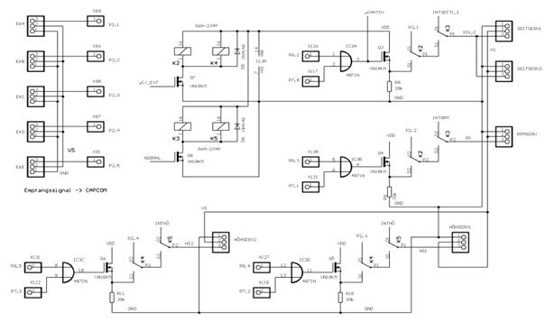
Fig 24: Part 2 of the switch between Luftschiff-Startphasen -operation
and normal operation (LSB/NB-switch, part2)
Transition
from startup, after LSB or NB and between LSB and NB (see Figure 23):
The
PWM-signal of Fernsteuerungskanal 5 is from the output P2.5 of the
Fernsteuerungsempfangers on the entrance to the LSB/NB-switch (in Figure 24
with P2.5 refers). In the LSB/NB-switch is depending on the length of the
PWM-signal greater than 1.5 ms: LSB; smaller than 1.5 ms: NB) of the output 12
(C/_Ext) of his flip-flop module IC7B on high or low (see Figure 23) is set,
this line of the flip-flops, with the gate input is insulated (C/_Ext) of the
Fett-Kondensators Q7 (see 24) connected. The FET controls the relay K2 and K4,
and K2 can be either a interconnection of the Fernsteuerkanale 1 and 2 (P2.1
and P2.2) to the rudder and the engine or but the connection of the rudder and
the engine to the outputs P8.2, P7.0, P8.3 and P7.1 of the microcontroller, K4
has the same effect as K2, but not for the rudder and the engine, but for the
two Hohenruderhalften (elevators 1 And 2).mm
Transition
from NB or LSB Notsteuersignal-Erzeugung - level 2 (see Figure 23):
If neither PWM signals at the
output of the ACU concerns, nor PWM signals over Fernsteuerungskanal 5,
interrupt the relay K3 and K5 the connections to the relay K2 and K4 and connect the actuators with the Block "
Notsteuersignal-Erzeugung - level 2 ".
Table 3: summarizes the inputs and outputs of the LSB/NB-switch together:
In
Abschn.3.3 was the architecture of the " Steuersignal-Erzeugung raised
before the description of the off-the-job training Shelf-Hardware and the
design of the software components of the " Steuersignal-Erzeugung "
is moved, here is to again on the architecture of the "
Steuersignal-Erzeugung " be received, and also some of the things added:
The Block
"Steuersignalerzeugung" generated depending on the operating status
on various way control signals (PWM signals), the directly the actuators
(engine, servos) response:
�
In normal
operation A gets the "Steuersignalerzeugung" commands from
manifold of the " Basisbetriebszustands-Einstellung " and generates
control signals (i.e. , PWM signals)
�
In normal
operation B are control signals (i.e. , PWM signals) from
Fernsteuerungsempfanger (by the microcontroller through) activated and
forwarded to the actuators, the Microcontroller is used here as
Signal-Begrenzer and observers.
�
At the system startup to the normal operation B
is initialized, if on channel 5 "Normal mode" is set, and the
further operation may, at any time from normal operation B switch to normal
operation a be and vice versa, and this is done by setting from the
N/R-machine from the N/R-computer receives this information on his communication
system from the ground (not from the remote control).
�
If in normal operation A or normal operation B
due to the failure or failure of the N/R-computer and/or of the
Fernsteuerungsempfangers no more signals the microcontroller on the input port
of the microcontroller, will be moved to the State "
Notsteuersignal-Erzeugung - level 1 ", in which the microcontroller of the
"Steuersignalerzeugung" autonomously PWM signals to the actuators
generated and there is, so can the time of the failure of normal operation and
normal operation B with a defined PWM signals are bridged.
Fig 25: Block diagram of the "
Steuersignal-Erzeugung "
Fig 26: finite state machine for the
" Steuersignal-Erzeugung ". (See Figure 13 in section 3.6 ).
The
Steuersignal-Erzeugung is realized by a software on the microcontroller
80C167CR-LM is running, and the microcontroller is located on a Testbord, the
company was purchased PHYTEC. All the required peripherals are also located on
the plate.
The
monitoring of the pulse width is particularly important for the proper function
of the circuit, because of these data have the dynamic and the stationary
behavior of the airship (alternative Lotte) abhanget, faults can also
indirectly in the Aktorenbereich pulse produced by the be discovered.
The 4
channels of the receiver are connected to the lower 4 pins of the Port 2
connected. In Figure 27 is the program for the 4 inputs of the �c. The pulse
lengths are programd with the help of the Capcom1 unit measured
Fig 27: for the
Aktorik-Ansteuerungsprogramm Programmablaufplan on the �C
Table 4: shows the channel no.., and the corresponding
connections and Capture-Register
The
subunit CAPCOM1 consists, as previously mentioned in chapter 2 was, from the
two timers T0 and T1, the program was only one timer necessary and 4
registers (see Table 4) .
Be the 4
tabs in the Mode Capture (used to recover) is used, which means that the
register at each rising or falling edge on these inputs corresponding the the
recovered CCxx meter readings of the Timer T0 Record. Your Operating Mode
(Mode) in a 4-bit-long field in a of the Betriebsartregisters CCM0.
The
control register CCMx set the operating mode of each of four Captur/ compare
channels each firmly.
����������� Selection of the operating mode
CCMODx
���������������������������������� 001 : Capture
on the rising edge at the terminal CCxIO
���������������������������������� 010 : Capture
the trailing edge at Port CCxIO
���������������������������������� 011 : Capture
on both flanks at Port CCxIO
����������� ACCx ����������������������� assignment the timer: 0 = T0 or "T7
", 1 = T1 or T8
The CCM0
register is in the main function under void main (void) with CCM0 = 0x1111 set,
and so is with each rising edge on these inputs a corresponding interrupt
(CCxIC) is triggered, and for processing led to the first interrupt
routine.
First interrupt routine:
In
the first interrupt routine is
the Timer T0 and its 3,000 Nachladeregistern the value given to the same period
of 25 ms to reach the measured signals, then with T0R = 1 started, before the
control register should T01CON = 0x0000 in the main function will be programd,
the CCM0-Register is here with 0x2222 programd to the falling edges to capture.
And so with the falling edge
on the inputs a corresponding interrupt (CCxIC) triggered and the current
counter of the timer T0 to the corresponding Capture-Register CCxx saved (see
Figure 28). The triggered Interrupt leads to the processing of the second
interrupt routine.
Fig 28: Capture Mode
Second Interruptroutinen:
In the second interrupt routine , the value of the Timer T0 in the
moment in the Capture-Register saved and then to the global variable copied
CC_Nx. The CCM0-Register will be programd to rising edge, and the pulse length
is measured not only easy, but it must also be made in a statement, and this is
why the CC_Nx values with two constant T1x_MIN and T1x_MAX compared (see
program and Figure 29). The two constants are used to limit the pulse signals
between 1.2 ms and 1.8 ms, and that makes it possible to get the
Hohenruderausschlag limited by the software.��������
�� ������������������������������������If (CC_N > T1_min )
����������������������������� ������������������������������ {
���������������������������������� ������������������ CC18 = T1_min;
���������������������������������� ������������������ P82 = !P21;
�������������������������������� ������������������������������� }
��������������������������������������������
Else if (CC_N < T1_max)
�������������������������������� ������������������������������� {
���������������������������������� ������������������� CC18 = T1_max;
�������������������������������� ������������������������������� }
���
���������������������������������������
Else
�������������������������������� ������������������������������� }
���������������������������������������� �������P82 = P21;
Fig 29: T0 and CC1 in capture mode
Third interrupt routine:
In this
interrupt routine, the contents Compare-Register , of the same value of 1.8 ms
is, with the Timer T1 within second interrupt routine compared. In conformity
is a Interrupt CCX * IC is triggered and this will of the appropriate output
port (P8X= 0) set to zero, thus the PWM-limited pulses.
At 1.2
ms, with the smaller T1_min the Compare-Registers/1.8 ms and when is with the
larger value of T1_max the Compare-Registers compared.
����������������������� ������������������ CC18_isr void (void)
interrupt 0x32
�������������������������������������������� {
�������������������������������� ������������������������������� P82 = 0;
�������������������������������� ����������� ��������������������CC21 = T1_max;
�������������������������������������������� }
Fourth interrupt routine:
For the
monitoring of the input signals is the fourth interrupt routine with the Timer T2 initialized . The
initialization of the interrupts is done after the setting of the mode of the
timer T2CON = 0x0003 ( period = 210 ms ) and with T2R = 1, the timer is started
and with a 0 the interrupt processing given freely, and the timer T2 is in the
second Interruptroutinen every time on the T2 = 500 reset, which means that the
third interrupt routine is not
triggered, only if no rising or falling edge within the period of the timer is
important, in the T2 interrupt routine, constant
PWM
signals generated by the PWM unit.
Test routines
For the
tests, which are described in chapter 2, test programs have been created.
Test
1 is used
For the
measurement and evaluation of the Mikrocontroller-Eingangssignale (PWM signals)
on board, the come from the recipient and
To test
the of the PWM-unit of the microcontroller produced
PWM signals.
Test 2 will test the constancy of the
supply voltage of the �C, and the other components of the
Aktorik-Ansteuerungsbaugruppe .
The full
code is included in Annex B listed.
With
this unit in the event of an emergency are constant PWM signals generated (30),
if the recipient for some reason no sending them signals to the outputs, this
unit has 4 channels, each of the 4 channels contains its own Timer PTX, the
from the CPU-measure or a divider on the counts receives(Table 4). The period
of the signal results from a comparison of the current counter with the
Periodenregister PX, the Low-Zeit from a comparison with the Pulsweitenregister
PWX (see C program and 30).
Table 5: shows the DCLS Einheit-Ausgange and
their corresponding Timer
�����������������������
����������������������������� T2_isr void (void) interrupt 0x22
�������������������������������� {
����������������������������������� P7X = 0; //
P7.x is output
��������
������������� �����������PX = 7800; // Max Period
����������������������������������� PWX = 7372)
and strong support ; // Initial value (high flank)
����������������������������������� PWMCON0 =
0x0044; // Timer and CPU-to-measure : Age 64 (210 ms)
�����������������
������������������PWMCON1 =
0x0004; // outputs with mode 0 Free
�������������������������������� }
Fig 30: PWM-production in the Mode PMX 0

Fig 31:
for the Blockdiagram Notsteuerungsbaugruppe
Fig 32: Monitoring of the control
signals (PWM signals) at the output (CAKTIV) of the ACU and the channel5-output
of the Fernsteuerempfangers (P2.5)m
If to
P2.5) and mCAKTIV
no signals are present, the OR-link to output 3 set to "Low" and
flip-flops to input 12 of the IC5B of the " Basisbetriebszustands-Einstellung
" (see Figure 23). The output 9 of the IC5B is to input 11 of IC9B (see
Figure 29) has been set and now led the production of Notsteuerungssignalen -
level 2.
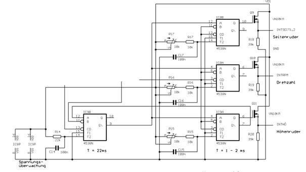
Fig 33: Notsteuerungsignal-Erzeugung -
level 2
As
already mentioned above, output 9 of the IC5B of the "
Basisbetriebszustands-Einstellung " (see Figure 23) with input 11 of IC9B
(see Figure 33) now connected and led the production of Notsteuerungssignalen -
level 2, and this is done as follows:
Output 9
of the IC9B triggers each of the input A of the three flip-flops IC8B, IC8A and
IC9A. The output of the latter three flip-flops is each with the gate of a FET,
the gate signal of the reinforced forwards to the respective actuator, PWM
signals are caused by the combination with the clock of the two flip-flops
expands (IC9B and IC8B, IC9B and IC8A, IC9B and IC9A).
Figure 34: One of the three generated PWM
signals, which is generated by the combination of the clocks of the two
flip-flops expands is created (see text)
The PWM
of the three generated PWM signals (in the picture as an example T2-T1
for one of the three generated PWM-signals) can before each use of the
airship by the potentiometer P15 P16 and P17 be set (Figure 34). This can the
Notsteuersignal-Erzeugung - level 2 of the conditions of the respective mission
be adapted.
The
condition " Luftschiff-Startphasen -operation" are the channels 1-4
(in Figure 24 are you with P2.1-P2.4 and higher) of the Fernsteuerempfangers
placed directly to the actuators, and this is done, if K2, K3, K4 and K5 are
activated accordingly (see left and right lower half of the 24), i.e. , P2.1 is
directly with SEITSERV1 and SEITSERV2 connected, P2.2 is directly with RPMSERV
(engine) connected, P2.3 is connected directly with H�HSERV1 and P2.4 and
higher H�HSERV2 is directly connected with.
i.e. here
is not a new circuit necessary.
The
blocks "Voltage regulation", " Basisbetriebszustands-Einstellung
" and " Notsteuerungs-Baugruppe " are realized on the circuit
board 1 (see section 3.6 ), Figure 35 shows the layout design of Board 1.
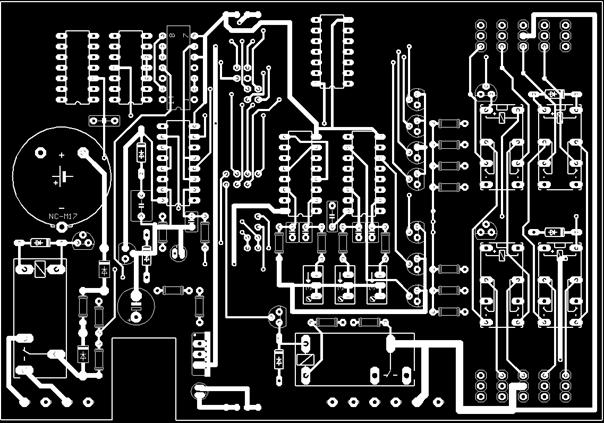
Fig 35: the layout design of board 1�����������
The both circuit boards of the
ACU
Fig 36: the two boards (1 and 2) to the ACU
Figure 37: the receiver and the actuators (engine,servos) are connected
to circuit board 1.
Figure 38: Testplatzaufbau
Fig 38
shows the in the experiments and the development of the program used for the
ACU devices. The PC is the ACU via a serial interface (RS232) connected to the
PWM signals to make visible, an oscilloscope is used.
The ACU
is particularly sensitive to static electricity, which is why it is important,
this assembly to a suitable place to be during the experiments, in the housing
for the embedded system is a Versorgungsspannungserzeugungseinheit (right-hand
side of the figure) is installed, in order to able to forego on batteries.
The
output values (counter values the Compare-Einheit/swap is performed on the
ACU-microcontroller for the rising and falling edges of visualized on the
oscilloscope signals) over a serial interface sent to the PC, it is calculated
and the pulse width on the PC-screen made visible, the three following signals
are made visible at the same time on the oscilloscope.
�
The ACU-input signal to channel 5,
�
A selectable output signal of the ACU and
�
A selectable input signal of the ACU.
On the
PC-screen pulse width can be permanently on the oscilloscope with
the pulse width of the respective signal shown by the user are compared,
so you can while the program runs directly determine whether the program
expires without fault, this data are of great help in the detection of the
error with unstable program.
The two
most important experimental data are visualized on the oscilloscope and the
length of the period of the distance between the rising and the falling edge of
the the PWM-signal.
At the
time of the implementation of the tests was the ACU Mikrokontroller-Platine so
faulty that input only P2.4 and higher (channel 4), exit 4 (control of elevator
clattering 1) and channel 5 did, so no signals from other A and/or outputs
(control of the rudder, of the engine, ... ) will be tested, but are on the
other a and/or outputs to the expected signals similar to those of each input 4
and Output 4.
In the
following tests the signals to Input 4 and Output 4 in various operating
conditions as measured. The current operational status is also measured by the
signal set to channel 5, the 2 possible modes of channel 5 (1, by the recipient
pulse width less than 1.5 ms: normal operation; 2, pulse width from the
receiver greater than 1.5 ms: Luftschiff-Startphasen -operation) are by a
switch on Fernsteuerungssender (on the ground) set by hand.
The
following are the different conditions under which the different tests ran:
Test 1:
pulse width of channel 5 of the receiver less than 1.5 ms: -> normal. The
ACU is under the condition when you turn on "normal" to the normal
mode B initialized. Under this condition runs test 1.
Test 2:
pulse width of channel 5 of the recipient greater than 1.5 ms:
Luftschiff-Startphasen -operation.
Test 3: there
is no signal from the receiver: -> It is a signal to output generated by the
microcontroller 4 ( Notsteuersignal-Erzeugung - level 1)
Test 4:
ACU Mikrocontroller-Platine is removed from the system: ->
Notsteuersignal-Erzeugung - level 2 is activated, a signal generated by the
Notsteuerungsbaugruppe is to output 4 to.
Test 5-1,
Test 5-2: operation B, i.e. the microcontroller directs the PWM-signal from the
remote control next (input 4 on the outcome 4)and, in addition, the pulse
width of the signal limited, i.e. , the signal on output 4 (channel 4) is in
contrast to the signal at the input (up or down to) Limited, unlike the limit
test 1 is indeed in the visible, because the input signals outside the limits.
Test 6:
between normal operation and normal operation A B is changed by the
corresponding information from the N/R-machine to the microcontroller of the
ACU is given, the N/R-computer receives this information via the communication
system from the ground, in test 6 this will be simulated by two different keys
on the lab computer, the serial interface is connected to the ACU, and of the
the N/R-simulated by computer, will be activated, if the A button is
pressed, the system is intended to go to the normal mode A, in the other key is
to control the system to normal operation B go. The correct transfer of
information from N/R-machine to the microcontroller and the correct
response is with the help of appropriate LEDs on the
Mikrocontroller-Platine (board 2) simulates. These lights depending on the currently
valid condition.
In the
Test-Abbildungen are from top to bottom to see the following signals:
1. CH 1: channel 5
at the entrance of the ACU
2. CH 2: channel 4
at the entrance of the ACU
3. CH 3: Channel 4
on the output of the �C
4. CH 4: Channel 4
on the output of the ACU
The
channel 5- switch of the remote control on the ground, is to "pulse width
less than 1.5 ms" provided.
It is the
normal case B (control signals from Fernsteuerrungs-Empf . will be give to the
microcontroller, the passes on this to its output) tested, with the
Fernsteuerungsknuppel is a certain deflection of the commanded Hohenruders. This
specification is on channel 4 sent.
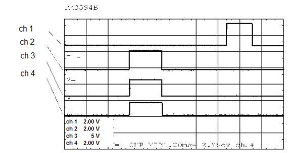
Fig 39: Test 1
CH1 = channel 5; CH2 = input signal from channel 4; CH3 = output from the
microcontroller; CH4 = output channel 4 of the ACU
Figure 39
shows that the pulse width of the channel 5 less than 1.5 ms (1.2 ms) is, this
is normal operation B is set, and the PWM of the PWM signals at the input and
output of the channel 4 are identical (1.5 ms), and so has the �C the PWM
signals without modification of the output of the ACU redirected. The
results came out as expected.
The
channel 5- switch of the remote control on the ground, is to "pulse width
greater than 1.5 ms" position, this will the Luftschiff-Startphasen
-operation (the PWM signals are Fernsteuerungsempfanger directly to the
ACU-outputs passed on) set, otherwise runs Test 2 as the above test 1.
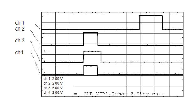
Fig 40: Test 2 CH1
= channel 5; CH2 = input signal from channel 4; CH3 = output from the
microcontroller; CH4 = output channel 4 of the ACU
In Figure
40 is the PWM-signal to channel 5 (CH 1) 2 ms long, and as expected, this
Luftschiff-Startphase -operation set by the �C, the PWM on the lower limit
of 1.2 ms limited, and because the input signal (CH2) only 1.0 ms long and thus
smaller than 1.2 ms, it is to 1.2 ms at the �C output extended (see Ch 3). The
Luftschiff-Startphasen -operation however the signals directly forwarded and
unlimited on the ACU-output (CH4) is set, and the results in the figure are
consistent with what you would expect.
The PWM
signals from Fernsteuerungsempfanger (channel 1, channel 5) will not be
more to the ACU-inputs connected (this is CH2 dead, i.e. , in the Fig is not a
rash to see), thus a failure of the remote control will be simulated, and no
data coming from the R/N-machine.
Thus, the
level 1 Notsteuersignal-Erzeugung enabled.
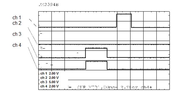
Figure 41: Test 3 CH1 = channel 5; CH2 = input signal from channel 4; CH3 = output
from the microcontroller; CH4 = output channel 4 of the ACU
As
expected, the �C with the help of his internal PWM unit PWM signals with fixed
pulsewidth created (CH3), the on the output of the ACU (Ch 4) concern.
In this
test, the " Notsteuersignal-Erzeugung - level 2" is activated, by the
circuit board with the microcontroller (Plate 2) from the ACU is mechanically
separated, this will simulate a failure of the microcontroller, in Fig. 42 one
sees that neither an input signal (CH2) is present, even at the output of the
microcontroller (CH3) a signal is present, even is the channel5-input signal
from Fernsteuerungsempfanger (CH1) to.
The
successful production of a PWM signal with the "
Notsteuersignal-Erzeugung Level 2" is shown by ch 4.
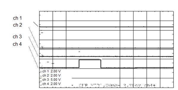
Fig 42: Test 4, CH1 = channel 5; CH2 = input signal from channel 4; CH3
= output from the microcontroller; CH4 = output channel 4 of the ACU
The
Pulsweiten-Begrenzung the PWM signals in normal operation B at the output of
the channel 4 tested.
By the
Fernsteuerungsknuppel, the maximum pulse (2.0 ms) (Test 5-1) and minimum pulse
width (1.0 ms) (Test 5-2.) The PWM-signal commanded. This is on ch 2 in
the two illustrations 43 and 44 to see.
In Figure
43 is the limitation of the PWM-signal to the upper limit of the pulse width
clearly shown: CH 2 (2.0 ms) is the unlimited signal, CH 4 (1.8 ms) is the
limited signal.
In Figure
44 is the limitation of the PWM-signal to the lower border of the pulse width
clearly shown: CH 2 (1.0 ms) is the unlimited signal, CH 4 (1.2 ms) is the
limited signal.
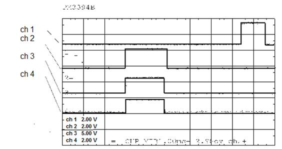
Figure 43: Test 5-1, CH1 = channel 5; CH2 = input signal from channel 4;
CH3 = output from the microcontroller; CH4 = output channel 4 of the ACU
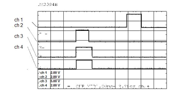
Figure 44: Test 5-2, CH1 = channel 5; CH2 = input signal from channel 4;
CH3 = output from the microcontroller; CH4 = output channel 4 of the ACU
In this work , a part-functioning
Aktorik-Ansteuerungs -unit (Actuator Control Unit (ACU) for the airship
"alternative Lotte" was completed, and the ACU
Fernsteuerungsempfanger get input signals of a or of a regulatory and the
navigation computer (R/N-computer) on board, depending on the operating mode
are in different ways by the ACU Anteuerungssignale for the actuators (Helm,
engine) is created, the ACU has a multi-level security system to R/N-the airship
crash or Kommunikationsverbindungsausfall defined for a time as possible to
control and, where necessary to bring safely to the ground.
At the time of submission of the thesis is the
data stream between R/N-machine and ACU has not yet been tested on correctness,
the there is a connection, but is has been verified and the data stream between
R/N-machine and ACU is to be tested during the integration phase, i.e. when the
ACU together with the other components of the Flugkontrollsystems (Flight
Control System (FCS) are joined together.
[ 1]
(C167) underlying hedged transaction Users Manual, Infineon AG, Munich, 3.1 edition; March
2000.
[ 2]
Schmitt G, "micro-computers with the Controller C167 ", Oldenbourg
Verlag, 2000.
[ 3]
Martin H. , "lecture notes for microcontroller C167 ", Institute of Computing Technology, Technical
University of Vienna, 2000.
[ 4] Bernd B. / Peter G. , "The Big
C167-microcontroller Operation", Gerber Verlag,
2001
Circuit
Design for the Versorgungsspannungs-Stabilisierung
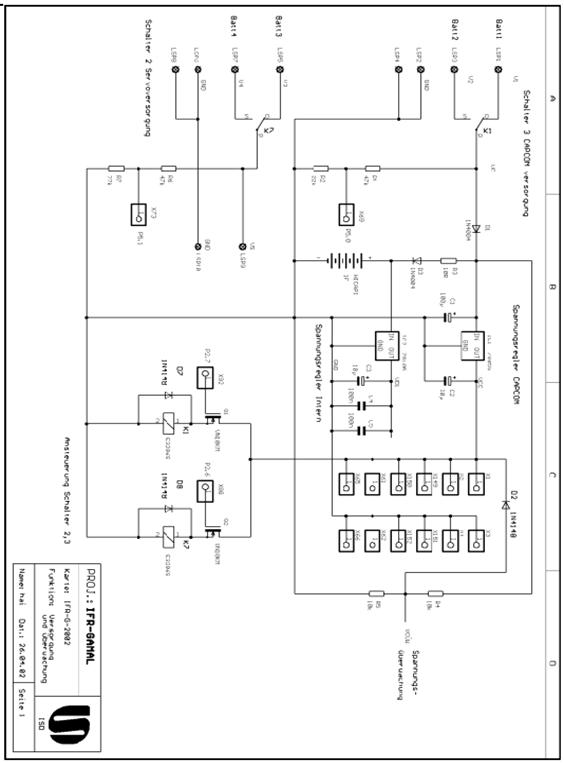
Figure
0-1: circuit design for the Versorgungsspannungs-Stabilisierung
Circuit for switch between Luftschiff-Startphasen
-operation and normal operation (LSB/NB switch, part2)
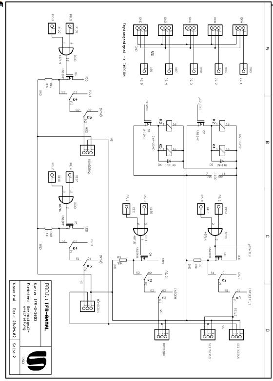
Figure 0-2: shift to switch between
Luftschiff-Startphasen -operation and normal operation (LSB/NB switch, part2)
Circuit
Design for the Basisbetriebszustands-Einstellung and the
Basisbetriebszustands-Einstellung
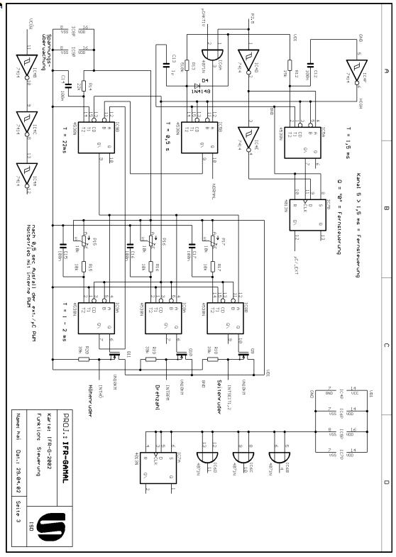
Figure
0-3: circuit design for the Basisbetriebszustands-Einstellung and the
Basisbetriebszustands-Einstellung
Test program 1
/ * Measure
of the length of time between successive flanks the entrance P2.3 * /
#Include
<REG167.h>
#Include
<intrins.h>
#Include
<stdio.h>
SFR Pam
Picon = 0xf1c4;
/ *
----------------------------------------------------------------------------------------
** The
direction of the ports in and out for those needing
* /
SBIT DP84) = DP8
^ 4;
SBIT P84) = P8 ^
4;
SBIT DP72 = DP7 ^
2;
SBIT P72 = P7 ^
2;
SBIT DP23 = DP2 ^
3;���������������������� �
SBIT P23 = P2 ^
3;������ �
Unsigned
int CC_N;
Unsigned
int flankennr = 0; / * distinguishes between 1ter and 2nd flank * /
Unsigned
int T_E= 0;
Const int
T1_min = 6000; / * constant to the decision on whether the timer should be
stopped * /
Const int
T1_max = 7500; / * constant to the decision on whether the timer should be
stopped * /��������������� �������������������������������� � ���������������������������������
/ *
----------------------------------------------------------------------------------------------
** Global
variables for the serial interface
* /����
Unsigned
int t0_inhalt_start = 0;
Unsigned
int t0_inhalt_stop = 0;
Unsigned
int steur_reg = 0;
Unsigned
int steur_zaehler = 0;
/ *
----------------------------------------------------------------------------------------------
**
Production of the PWM-signals from derPWM-unit
* /
Void t2_isr (void) interrupt 0x22
�������������������������������� {
�������������������������������� P72 = 0;
�������������������������������� PP2 =
7800;
�������������������������������� PW2 =
7372) and strong support ;
�������������������������������� PWMCON0 =
0x00ff;
������������������������������� PWMCON1 =
0x000F;
��������������������������������
�������������������������������� }
/ *
--------------------------------------------------------------------------------------------
**
Limitation of the pulsewidth of the PWM signals
* /
Void
cc20ISR (void) interrupt 0x34
�� {
�������������������������������� P84) = 0;
�������������������������������� CC20 =
T1_max;
�� }
/ *
--------------------------------------------------------------------------------------------
**
Programming the PWM signals at the entrance
* /
Void p23
(void) interrupt 0x13
� {�
��������������������������������
�������������������������������� Charbuff_tmp [
40];���������������
�������������������������������� Int I;
��� PP2 = 0;
�������������������������������� PW2 = 0;
�������������������������������� P72 = 1;
�������������������������������� P84) =
P23;
If (flankennr= =
0) ������������������������ �� / * First edge * /
� {
�������������������������������� T2 = 500;
��� T0rel = 3000;
��� T0 = 3000;
������������������������������� T0R
= 1;���� ���������������������������� / * starts timer T0 * /
�������������������������������� T0_inhalt_start
= T0;
�������������������������������� T7rel = 2950;
��� T7 = 2950;
�������������������������������� T7R = 1;
�������������������������������� CCM0=
CCM0 & 0x0FFF;
��� CCM0= CCM0| 0x2000;
�� Flankennr= 1;�
��������������� / * YES ->
There are still two more sides expected * /
�� }
� Else if (flankennr= = 1) / * Second flank * /
�� {
�����������������������������
CC_N = CC3;
����
T0_inhalt_stop = T0;
��������������������������������
CCM5 = 0x0005;�������
���� CCM0= CCM0 & 0x0FFF;
��� CCM0= CCM0| 0x1000;
�������������������������������� Flankennr
= 0;
�
���� If (CC_N
< T1_min )
����������������������������� � {
���������������������������������� CC20
= T1_min;
���������������������������������� P84)
= !P23;
�������������������������������� � }
���� Else if
(CC_N > T1_max)
�������������������������������� � {
���������������������������������� CC20
= T1_max;
�������������������������������� � }
���� Else
�������������������������������� � {
���������������������������������� P84) = P23;
�������������������������������� � }
�������������������������������� �
/ *
------------------------------------------------------------------------------------------
** The
serial interface
* /
��� If (( + +steur_reg) == 100)
���� {
������� For (i= 0; i< 100; i++)
���������������������������������� {
�� ����� sprintf(buff_tmp, "T0start:
%u;Tstop: %u;imp: %u\n",
���������������������������������������������������������������������� T0_inhalt_start,t0_inhalt_stop,CC_N
, steur_reg);
��������� Printf (buff_tmp);
���������������������������������� }
���� }
� }
}
�������������������������������
Void main
(void)
��������� ���{
�������������������������������� �� Flankennr = 0;��������� �������� / *
0.. there is still no flank occurred * /
��� �������������������������� DP72
= 1;������������� ����� �������� / * DP7.2 central as output * /
���������������������������������� DP23 = 0;������ �������� / * sets the direction of DP2.3 to
input * /
���������������������������������� DP84) = 1; /
* sets the direction of DP8.4 on output. * /
���������������������������������� Pam Picon =
Pam Picon | 0x3;
���������������������������������� CCM0 = 0x1000;
���������������������������������� CCM1 =
0x0001;
���������������������������������� T01CON = 0x0000; / * Timer 1 has
been with period (26 ms) initialized * /
���������������������������������� CC3IC = 0x0047;
���������������������������������� CC4IC =
0x0046;
���������������������������������� CC21IC =
0x0045;
���������������������������������� CC20IC
= 0x0048;
���������������������������������� T2CON = 0x0003;
���������������������������������� T2IC =
0x0044;���������
���������������������������������� T78CON =
0x0000;/ 0 1 00 0 000 0 1 00 0 000 26 ms * /��������������
�������������������������������� � T2R = 1;
���������������������������������� IEN
= 1;
�������������������������������� �� While(1) {
�������������������������������� �
�������������������������������� _idle_( );
}
}
Test program 2
#Include
<reg167.h>/ * Register Diffinitionen of the C167) * /����������������
#Include
<intrins.h>/ * bausteinspezifische functions * /��������������
#Include
<stdio.h>
/ *
---------------------------------------------------------------------------------
**
Initialization of the inputs and outputs
* /
SBIT DP26 =DP2 ^
6;
SBIT P26 =P2 ^ 6;
SBIT DP27 =DP2 ^
7;
SBIT P27 =P2 ^ 7;
SFR P5DIDIS =
0xFFA4;
Unsigned int
adc_kanal0[200];/ * buffer for the Wandlungeergebnisse * /��������
Unsigned int
adc_kanal1[200];/ * buffer for the Wandlungeergebnisse * /��������
Static unsigned
int steur_reg = 0;
Static unsigned
int steur_kanal0 = 0;
Static unsigned
int steur_kanal1 = 0;
Static unsigned
int pxt= 0;
/ * In the
AD-converter interrupt service routine, the Wandlungsergebnisse
� Read and in the field adc_werte copied and if the value in adc_werte 16
� Less than 496 (4.76 p. p. p. n V) is, is
therefore in this moment by high edge to P2.6 or higher a
� HRLY RATE be switched * /
Void adcisr
(void) interrupt 0x28
{
� Int I;
� Unsigned int test_1;
� Unsigned int test_0;
� Char buff_tmp[ 40];
� If (ADDAT & 0x1000)
� {
�������������������������������� TEST_0 =
ADDAT & 0x03ff;
���� Adc_kanal steur_kanal0+0 [ +] = ADDAT
& 0x03ff; / * result of a/d process * /
�������������������������������� If( test_0 < 800)/ * voltage
small e.g. 4 V * / ��������
��������������������������������� {����������
������ P26 = 1;������������������������� �� / * is available on the P7.8 1 (rising edge)
* /
��� �������������������������� }
������������������������������� Else
�������������������������������� ��{
�������������������������������� �� P26 = 0;
�������������������������������� �� }
� }
� Else
� {
���� TEST_1 = ADDAT & 0x03ff;
���� Adc_kanal steur_kanal1+1 [ +] = ADDAT
& 0x03ff; / * result of a/d process * /
����������������������������� �
�������������������������������� If(test_1 < 600)/ * voltage small
e.g. 4 V * /
���� {�������������������������
������ P27=0;/ * is available on the P7.8 1
(rising edge) * /�������������������������
���� }
������������������������������� Else
�������������������������������� {
�������������������������������� �� P27 = 1;
�������������������������������� }
��������������������������������
�������������������������������� }
� / *
--------------------------------------------
� From the �C ** data sent back to the screen
* /����������������������������
� If
((steur_reg) < 100)
� {
���� +
+Steur_reg;
� }
� Else if ((steur_reg) == 100)
� {
���� For (i= 0; i< 50; i++)
���� {
�������������������������������� ���� sprintf(buff_tmp, "Channel1: %u,
Kanal0: %u\n",
���������������������������������������������������������������������� Adc_kanal1
[i], adc_kanal0 [i] );
�������������������������������� ���� Printf (buff_tmp);
��� }
� }
}
/ *
--------------------------------------------------------------------
� ** With GPT1 is the conversion each time
after time start bestemmte
* /
Void gpt1T3
(void) interrupt 0x23
{
� ADST = 1; / * Conversion start * /
}
Void main
(void) {
����������������������������������������������
�������������������������������� DP27 = 1;
�������������������������������� P27 = 1;
�������������������������������� DP26 = 1;
�������������������������������� P26 = 1;
����������������������������� P5DIDIS
|= 0x0001;
�������������������������������� Adcon= 0xf221;
����������������������������� T3CON = 0x0002;
����������������������������� T3 = 0x0BDC;
����������������������������� T3IC = 0x006B;
����������������������������� T2CON = 0x0020;
����������������������������� T2 = 0x0BDC;
����������������������������� ADCIC = 0x004C;
�������������������������������� IEN= 1;
� ���������������������������� T3R
= 1;
�������������������������������� While(1){
�������������������������������� _idle_(
);
�������������������������������� }
}���������������������������������
Based on
the bachelor thesis of Rabih al-Farkh, "Development of
a communication interface for a measurement system", June 2002, Lebanese University � Tripoli/Lebanon, Faculty of
Engineering
Abstract
A communication system which includes a graphical user
interface has been developed to control a mobile sensor platform, and to
receive measurement data from this mobile sensor platform. The measurement
system is used to measure alternative energy resource values like solar power
and wind vector at different points.
Keywords:
graphical user interface, airship, transceiver, wireless communication,
V-model, structured analysis, structured design, software engineering.
Airships are becoming more and more important within
the last years. At the �Institut f�r Statik und Dynamik der Luft- und
Raumfahrtkonstruktion� at the University
of Stuttgart a solar
airship was built. In February 1992 the project �Solarluftboot� was initiated.
The purpose of this project was to find new materials, new construction methods
and a new concept for controlling and navigating an airship run by a solar
energy engine.
The �alternative Lotte� � a cooperation project
between the universities of Karlsruhe and Stuttgart and the Fachhochschule
Karlsruhe - is planned to be an experimental airship which can be controlled
directly from the ground (first step of implementation) or (second step of
implementation) fly automatically to specified coordinates. The energy supply
is going to be conventional batteries in the first step but it is planned to
switch to solar energy later. With �alternative Lotte� environmental data are
collected during the flight via different sensors which can be mounted on the
airship. In the first step the speed of the wind, the temperature and the solar
radiation are measured. Apart from that flight data such as acceleration,
angular velocity and azimuth angle are measured for navigation purposes.
The
software is developed using structured analysis / structured design (SA / SD).
This method is very common in industrial development processes as well. The
complete communication system is tested in a laboratory using two PCs and the
transceivers. The whole development process basically follows the known
V-model.
The task is
to develop a communication interface which is software running on a PC which is
connected with the transceiver on the ground. Apart from that a program which
is running on the board computer has to be developed. The purpose of this
program is to establish the communication between the sensors and the
transceiver on the �alternative Lotte� sensor platform.
So the diploma thesis can be divided into several
tasks:
�
Specification document, SA
diagram (Structured Analysis) and SD diagram (Structured Design) for the User
Interface.
�
Programming of the User
Interface using Visual Basic 6.0.
�
Specification document, SA/SD
for the communication protocol.
�
Programming of the
communication protocol with programming language C.
�
Programming of the protocol
for sending and receiving with an off-the-shelf transceiver cards.
�
Testing the communication
system with the User Interface.
After a short introduction some basic knowledge about
the used development method SA / SD, the V-model and some general information
about transceivers is provided.
In the third chapter a detailed description of the
user interface and the transceiver is given. Then the system architecture of
the whole system is presented.
Chapter 5 contains the SA, SD of the alternative Lotte
communication system and a brief description of the software implementation.
After that the development environment is explained.
The last chapter is about the tests that have been
done to verify the functionality of the communication system.
Detailed figures of the hardware and the code of the
software can be found in the annex.
The V-Model is an extensive collection of
knowledge about the best practices of software development. This knowledge can
be described as a process: In addition to the planned products and activities,
the V-Model also contains
information about the course the project will take. To this end, the process
standard includes which output products are to be created by an activity and
which successor activities need this product as input. This internal product
flow allows you to derive a chronological order for the activities.
The V model
is a logical product model. It describes the contents of the products which
have to be created during a software project and their relationships on a very
high level. However, in a real project the physical structure of these products
might (and in most cases will) be quite different [1].
Figure 2.1: The V�Model
The left
side of the V shows the products resulting from development activities: problem
description, user requirements, developer requirements, system design,
component design and component code. The products are not further described
here.
The right side of the V documents the construction of
the final system starting with individual components. The products on this side
of the V are called executable components, executable system, usable system and
used system.
Besides
development and constructional activities the V model also contains some
analytical activities: verification and validation.
Verification takes place after each development
activity. The output of the activity is verified against the input in order to
check if both actually match.
Validation happens after each construction step to
assure that the so far constructed system behaves as it should. It is therefore
tested against the corresponding product on the other side of the V model.
It should be emphasized that the V model is no
physical product model nor any kind of process or life cycle model. However,
due to its very general description, products used in a life cycle model can
always be matched with the products contained in the V model. Therefore, it can
be seen as a generic product model.
The V-Model
is a Lifecycle Process Model, originally developed to regulate the software
development process within the Federal Administration of the Federal Republic
of Germany.�
The V-Model
is composed of four submodels: software development, quality assurance,
configuration management, and project management.
The submodels are closely interconnected and mutually
influence one another by exchange of products and results. The software
development submodel develops the system or software. The quality assurance
submodel submits requirements to the other submodels and test cases and
criteria to assure the products and the compliance of standards. The
configuration management submodel administers the generated products. The
project management model plans, monitors, and informs the other submodels. Each
can be further decomposed. For instance, the software development submodel can
be broken down as follows (see [2]):
- System requirements
analysis and design.
- Data processing
requirements analysis and design.
- Software requirements analysis.
- Preliminary design.
- Detailed design.
- Implementation.
- Software integration.
- Data processing
integration.
- System integration.
In the seventies and eighties of the 20th
century Structured Analysis (SA)
was described by Yourdon, Constantine, and DeMarco. These practices became very
popular, and by the early eighties had a profound effect upon the definition of
analysis. SA was a technique in
which the requirements of the customer were broken down into a hierarchy of
functions. This breakdown was known as functional
decomposition . Datasets were specified in abstract (Bacchus-Naur) terms,
and their manipulation were depicted through functionally decomposed data flow
diagrams.
SA
was coupled to another practice known as Structured Design (SD). Indeed, the two were often
mentioned in the same breath as SA/SD.
SA described the data sets and data
transformations implied by the requirements. As such, SA described what the system
would do, albeit in very technical terms. On the other hand SD described the partitioning of the software into modules, and the flow of data
between those modules. Therefore an SD
was, more or less, a description of how a system would be structured to meet
the requirements. SA/SD contained a
practice known as The Transform Analysis
, which was used to convert the diagrams representing a Structured Analysis into the diagrams the represented a Structured
Design. This practice, and indeed much of the documentation of the period,
established the notion that the design was directly derivable from the analysis
by applying some simple transformation rules. This meant that the analysis was
really a preliminary description of
the design, requiring only a mapping operation to complete. The view of SA/SD was a remarkable change from the
systems analysis of the sixties. In the sixties no such mapping from analysis
to design was implied. The analysis simply described data sets
and their transformations without implying anything
about software structure. SA/SD also
implied a temporal constraint between analysis and design that was not
practiced by the Systems Analysis of the sixties. In SA/SD it was necessary to finish the analysis before the Transform
Analysis could be applied to translate the analysis into a design. Thus, SA/SD strongly reinforced the waterfall
model of development [3].
Figure 2.2: SA/SD (see [4])
There are
three wireless RF modules: transmitter, receiver and transceiver. These RF
modules are designed to serve as a tool for electronics design engineers,
developers and students to perform wireless experiments.
The
transmitter is used to transmit data and the receiver is used to receive data,
so they are used in application of one-way communication. The transceiver is
used to transmit and receive data, so it is used in application of two-way
communication. All of the RF modules which are used in this project have 9,600
bps serial interfaces at maximum. The used modules can communicate over range
up to 250 feet. Generally the range depends on the power and the frequency of
the RF module.
Radio frequency (RF) refers to electromagnetic waves
that have a wavelength suited for use in radio communication. Radio waves are
classified by their frequencies, which are expressed in kilohertz, megahertz,
or gigahertz [5].
The RF transceiver controls and modulates the radio
frequencies that the antenna transmits and receives.
The user
interface is the link between the user and the alternative � LOTTE, a
measurement vehicle for solar radiation and wind power. Its purpose is allowing
the user to control the alternative� �
LOTTE from the base station, so by using the User Interface, the user can set
data to the alternative � LOTTE (new position, new velocity ...) and get data
from the alternative � LOTTE (acceleration, angular velocity, azimuth,
temperature, wind vector, Solar radiation ...).
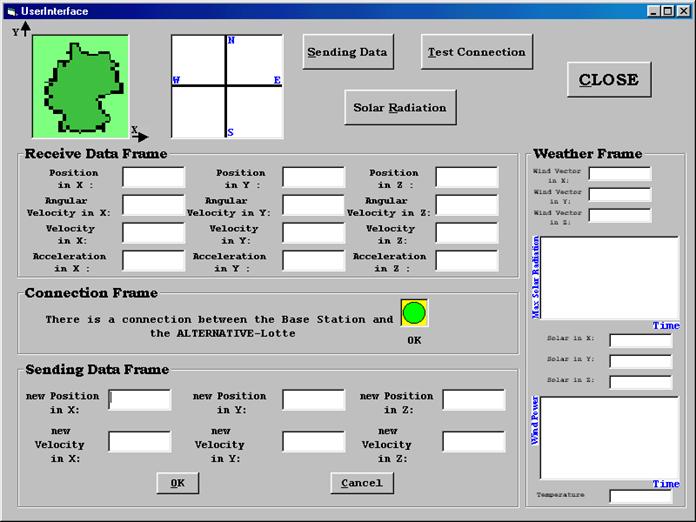 Figure
3.1: User Interface
Figure
3.1: User Interface
�
The user
interface contains a frame (Receive_Data_Frame) inside which, we find several 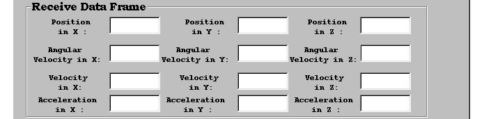
text boxes or labels.
Figure 3.2:
Receive Data Frame
�
These several
text boxes or labels are used to display the data that the base station
received from the alternative - LOTTE. These data are the data sensors
(acceleration in X, Y and Z, angular velocity in X, Y and Z, azimuth,
temperature, solar �Solar Radiation� and wind vector). As to the azimuth
parameter, it can not be seen by the user. It is used by the user interface to
display the direction of the alternative � LOTTE in a picture box.� These sensor data will be sent from the
alternative - LOTTE to the base station. The user interface uses these data to
calculate the velocity of the alternative - LOTTE in X, Y and Z and to
calculate the position of the alternative - LOTTE in X, Y and Z.
�
The user
interface contains command button shown below, this command button is used
whenever the user wants to send data (commands) to the alternative � LOTTE.
When the user presses this command button,�
a Send_Data_Frame will be displayed, (Sending_Data_Frame). The commands
that the user can send to the alternative � LOTTE are the new position in X, Y
and Z, and the new velocity in X, Y and Z.
Figure 3.3: Sending Data Button
� The
user interface contains Sending_Data_Frame, in this command frame, we find
several text boxes that are used by the user to put the data (commands) that he
will send to the alternative � LOTTE. These data (commands) are the new
position in X, Y and Z, and the new velocity in X, Y and Z.
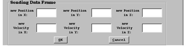
Figure 3.4: Sending_Data_Frame
�
The user
interface contains picture box that is used to display the position of the
alternative � LOTTE on a map (two dimensions x, y). In this picture
box the user will be able to see the position of the alternative � LOTTE during
its flight.
Figure 3.5: PictureMap
� The
user interface contains another command button. The function of this command
button is to test if the connection between the base station and the
alternative � LOTTE is OK. The result
is displayed in the Connection_Frame. In fact, the connection is always put to
the test whenever the user receives data from the alternative � LOTTE (which
means that the connection is OK). If
the user wants to make sure about the connection at any time all he has to do
is to press the Test � Connection Button.

Figure 3.6: Test-Connection Button
�
The user
interface contains a Connection_Frame that is used to tell the user that the
connection is OK while the alternative - LOTTE is in the air. In case there is
a problem in the connection between the base station and the alternative -
LOTTE, it is displayed in this frame, and the user would be able to see that
there is a problem.
Figure 3.7: Connection Frame
�
The user interface contains a picture box that is used to display the
direction of the alternative - LOTTE while it is in the air. The user interface
will get the azimuth from the alternative � LOTTE and use this parameter to
display the direction of the alternative � LOTTE.
Figure 3.8:
PictureDirection
�
The user
interface contains a weather frame that is used to tell the user the status of
the weather while the alternative � LOTTE is in the air. In this frame, the
user can observe the temperature, the wind vector, and the solar radiation
(solar radiation in X, Y and Z). The user interface get these data from the
sensors data.

Figure 3.9:
Weather Frame
�
The
user interface contains a third command button. The function of� this command button is to display the solar
radiation in front of the user in three dimensions. When the user press this
button, he will see the position of the alternative � LOTTE in three dimensions
with the value of the solar radiation in each position.
Figure
3.10:� Solar Radiation Button
�
When the user
presses the Solar Radiation button, the figure shown below shall be displayed :
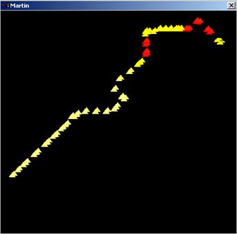
Figure
3.11: Solar Radiation show
In this
figure, the position of the alternative � LOTTE is displayed with the power of
the solar radiation, the color at the position shows the intensity of the solar
power at this point.
The goal
of this transceiver is send and receive data between the Base station and the
alternative � LOTTE. There are two transceivers, one is connected to the base
station and the other is connected to alternative � LOTTE.
In each
frame, the transceiver processes the data internally and input/output user
data. User data can be specific by user. In general, data is send and receive
as �packet�.
�
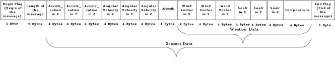
The form of the telegram that the base station receives from the
alternative � LOTTE is :
Figure
3.12: User Data Protocol _ Receive Message
�
The Begin flag is the beginning of the telegram (message) and the
length of this command is 1 byte (8 bits). It is a special byte that the user
uses to tell the alternative � LOTTE and the base station that it is the
beginning of the telegram (message).
�
The information length of the
telegram is on 2 bytes, and it contains an information about the length of the
telegram (message) that the base station receives from the alternative � LOTTE,
or sends to the alternative � LOTTE.
�
The sensors data contains
information about the acceleration in X, acceleration in Y, acceleration in Z,
angular velocity in X, angular velocity in Y, angular velocity in Z, the
azimuth, wind vector in X, wind vector in Y, wind vector in Z, solar in X,
solar in Y, solar in Z� and the
temperature. Each information is in 4 bytes and the type of� this data is float.
�
The End flag is the end of the telegram and the length of this command
is 1 byte. It is a special byte. So when the base station or the alternative �
LOTTE receives this byte, it knows that this is the End of the telegram and it
waits for another telegram from the alternative � LOTTE.
The form of the telegram (message) that the base
station sends to the alternative � LOTTE is :
Figure 3.13: User Data
Protocol� _� Send Message
The sent and the received telegram have the same
protocol (Begin_Flag , Length of the Telegram, Data or Commands (information)
and then the End_Flag). We can send the begin flag at first, then the length of
message (commands), then the commands (which gives the new position and the new
velocity), and finally the end flag to tell the alternative
� LOTTE that the telegram is finished.
Handshaking
refers to the internal communications protocol by which data is transferred
from the hardware port to the receive buffer. When a character of data arrives
at the serial port, the communications device has to move it into the receive
buffer. A handshaking protocol ensures that data is not lost due to a buffer
overrun, where data arrives at the port too quickly for the communications
device to move the data into the receiver buffer.
The purpose
of the user interface is to control the alternative � LOTTE from the base
station and the purpose of the transceiver is to send and receive data between
the base station and the alternative � LOTTE. The connection between the user
interface, the transceiver and the whole system is shown in the figure below :
Figure 4.1:
System Connection
This figure shown above describes the connection
between the PC in the base station which contains the user interface program
and the transceiver, and the connection between the embedded system in the
alternative � LOTTE and the other transceiver. This connection is done through
the serial port.
Apart the connection between the embedded system in
the alternative � LOTTE, the transceiver card and the sensors card is shown in
the figure above. In fact the sensors card is connected to the microcontroller
which is connected to the embedded system through the serial port. The purpose
of the microcontroller is to transfer the sensors data from the sensors card to
the embedded system. The embedded system gets these sensors data from the
serial port which the microcontroller is connected to and sends these data to
the serial port to which the transceiver card is connected.
The transceiver gets these sensors data from the
embedded system through the RS232C connector, then the data are stored in
internal buffer. After the transceiver checks that the carrier frequency to be
set is not used on air, these data will be sent to the base station using one
of the� channels frequencies between the
433.200 � 434.775 MHz. The same thing is done when the transceiver gets data
from the base station and will sent to the alternative � LOTTE
The modulation used is the FSK modulation (Frequency
Shift Keying), this type of modulation enables transmission at a maximum of
9,600bps. Also when multiple channel are to be used simultaneous
or if high communication standards are required, the MSK modulation enables
transmission at a maximum of 2,400bps.
Figure 4.2: The �alternative
Lotte� Communication System
The development has been done on a PC with AMD � k5 tm
processor, AT / AT compatible, 64 MB RAM and a PC with a PENTIUM � S processor 100 MHz,� 96
MB RAM.
The following software tools have been used for the
development:
�
MS Windows 98, MS Windows
2000, MS Office 97 and MS Office 2000.
�
Windows 2000 server for
workflow Management, Linux.
�
MS Visual Basic 6.0 language
and C language. (program C is done under VxWorks).
�
Visual Basic 6.0 compiler for
Visual Basic program.
�
"Gcc" compiler for C
program under UNIX.
�
Tornado 2.0 environments� for C program.
�
VxWorks 5.4 compiler for C
program.
�
Optional : MS Visio 2000 for
the graphical visualization of processes, Structured Analysis (SA) /� Structured Design (SD).
Figure 6.1: Context
Diagram
� The DISPLAY is the screen of a PC� in the base station that can be used to
observe the received sensors data. These sensors data are received from the
alternative � LOTTE using the serial port of the PC.
� The KEYBOARD is used by the user to write
the commands that he wants to send to the alternative � LOTTE. These commands
are sent to the alternative - �LOTTE
using the serial port. In fact, whenever the user wants to send commands to the
alternative � LOTTE, the user interface will send them to the serial port.
� The SERIAL PORT is the peripheral between the user
interface and the alternative � LOTTE. So by using the user interface, we can
say that the user will get data (from the alternative � LOTTE) and set data or
commands (to the alternative � LOTTE).
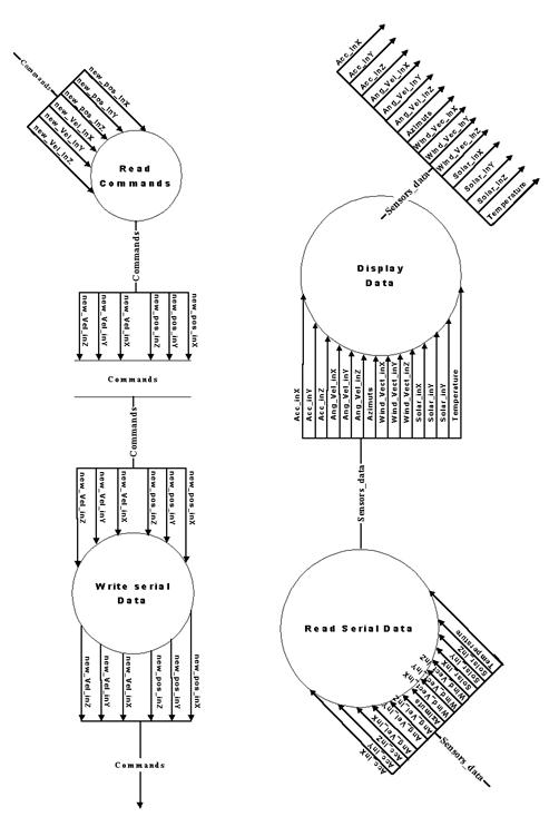
Figure
6.2: data flow diagram (DFD) of the process �User interface�
In this second diagram, we can see all the
functions that the user interface can perform .
� Some remarks
for structured analysis (SA) convention:

The symbol����������� means that we have a process and
this symbol
 �����������������������
means that we have a storage.
� In
the second increment a security layer is added to the communication protocol.
The commands that the base station sends to alternative �LOTTE will be
acknowledged. If the acknowledgement fails the commands are resent.
|
ID
|
Features
|
Increments
|
|
01
|
� Send commands to the alternative � LOTTE
� Receive data from the alternative � LOTTE
|
1
|
|
02
|
� Save Commands that the user sent to the��������������� alternative � LOTTE.
� Waiting for an answer from the
alternative
� LOTTE about what it has Received.
� Compare this answer with the Telegram (message) that the user sent.
|
2
|
|
03
|
� Send commands with saving it to compare with the answer from the
alternative � LOTTE.
� Receive data from the alternative � LOTTE.
|
������������������� All
|
Some
remarks for structured Design (SD) convention:
The
symbol����������������������������� means
that we have a function, and in this symbol we can find the
same name of the function used in program.
this
relation��������������������������������������������������������������
���means that the function1 calls
function 2.
 The symbol������������ describes
the return value of the function
The symbol������������ describes
the return value of the function
The
symbol������������ describes the input
parameters of the function.
Figure 6.3: Structured Design
(SD) diagram for the user interface
Description of the
functions
MSCOMM
This is an
OCX (Microsoft Comm Control 6.0) which contains all functions that the
programmer can use when he� wants to
program the serial port. Using this OCX, we can manage the serial port from
Visual Basic which means that we can open the port, put the settings of the
port, read from serial port and write to serial port ... .
UserInterface
Load
This
function runs automatically when the user runs the Program. The purpose of this
function is to give the MSCOMM the number of serial port that the user will
open and the settings and the InputMode. It will also enable the TimerRun_R and
testing the status of the serial port.
Timer_Run_R
This
function contains the interval which the user interface uses to read data from
serial port if this serial port was not busy. The serial port being busy means
that it is not used at the moment. For example, if we define the interval time
like one second, so every one second the program will read data from serial
port. Of course these data are the sensors data, and it contains information
about the acceleration of the alternative � LOTTE and the angular velocity, the
azimuth, the solar, the wind vector, and the temperature.
Read_Data
The purpose
of this function is to read sensors data from serial port and to use these data
to calculate the velocity of the alternative � LOTTE and its position. After
that it sends these data to� the
Receive_Data_Frame which is then displayed in front of the user. Of course the
user can not change these data, he can only see it. (Of course this requires
that the serial port is not busy doing any other function like sending commands
to the alternative � LOTTE, or testing the connection between the base station
and the alternative � LOTTE).
Write_Commands
The purpose
of this functions is that the user will be able to send commands from the base
station to the alternative � LOTTE, using the serial port. The user can write
commands after disabling the TimerRun_R. but if the TimerRun_R is enabled, this
means that the serial port is used only to Read_Data.
C_Send_Commands
The purpose
of this function is to enable the Sending_Data_Frame that it used by the user
to write the sending commands (new position in X, Y and Z, and new velocity in
X, Y and Z) that he wants to send to the alternative � LOTTE.
Send_OK
This
function will confirm that the user wants to send the commands that he writes
in the Sending_Data_Frame to the alternative � LOTTE after testing the status
of the serial port. This is because the serial port maybe busy doing another
function at that� time like receiving
data from the alternative � LOTTE ... .�
Send_Cancel
This
function is used by the user if he clicks the Sending Data Button and then he
changes his mind and does not want� to
send commands to the alternative � LOTTE. So this function will disable the
Sending_Data_Frame, and enable the TimerRun_R ( which means that the serial
port is not busy sending commands right now, but rather the program is enable
to read sensors data ).
C_Connection
The purpose
of this function is to test the connection between the base station and the
alternative � LOTTE. It refreshes the Connection_Frame and gets the status
connection from the Read_Data Function. It also displayed the status of the
connection on the Connection_Frame.
PictureBox_Position
The purpose
of this function is getting data from the Read_Data function (position in X,
position in Y) and displaying the position of the alternative � LOTTE on the
map.
PictureBox_Direction
The purpose
of this function is getting data from the Read_Data function (Azimuth) and
displaying the direction of the alternative � LOTTE in the PictureBox.
Calculate_Velocity
The purpose
of this function is to get the Acceleration from the Read_Data function and
calculate the velocity of the alternative � LOTTE in X, Y and Z and gives this
information to the Receive_Data_Frame that it displays.
Calculate_Position
The purpose
of this function is to get the velocity from the Calculate_Velocity and
calculate the position of the alternative � LOTTE in X, Y and Z and gives this
information to the Receive_Data_Frame that it displays.
TxtCodeHex2Dec
The purpose
of this function is to get the sensors data from the Read_Data function and to
convert this data from the hexadecimal format to the decimal format.
TxtCodeDec2Hex
The purpose
of this function is to get commands from the Write_Commands function and to
convert this commands from the decimal format to the hexadecimal format.
FormPosition
This
function run when the user press on the PicturePosition if he wants to see a
large view. It contains a large picture box that inside it the user can show
how the alternative � LOTTE change its position.
FormDirection
This
function run when the user press on the PictureDirection if he wants to see a
large view. It contains a large picture box that inside it the user can show
how the alternative � LOTTE change its direction.
Solar_Radiation
This
function run when the alternative � LOTTE finishes its travel. It takes the
position in X, Y and Z and the Solar Radiation in X, Y and Z from the Read_Data
function and uses these parameters to put the position of the alternative �
LOTTE in the three dimensions with the value of the solar radiation in each
position. The color of the position (point of position) changes with the value
of the solar radiation.
Jet
This
function run when the user press the solar radiation button. It takes the
parameters (position in X, Y and Z and the solar radiation) and puts it in a
three dimensional figure.
The whole
VB program code is in Annex E.
In this
paragraph, the important things done in the software part will be described. At
first, when the user interface program is used, the user has to care about
these commands :
� MSComm1.CommPort
= 3���� (line of code: 132)
this
command is used to open the serial port number 3. Changing the number of the
port is allowed. [6]
After that
the initialization of� the baud rate of
the serial interface, the parity status, the data length and the stop bit will
be done as below :
� MSComm1.Settings
= "9600,E,8,2" ���� (line of code: 133)
Then the
initialization of the handshaking protocol is done by this command :
� MSComm1.Handshaking
= comRTSXOnXOff������ (line of code: 134)
When the
handshaking is set to the value shown above, the RTSEnable property will be set
to TRUE as shown below :
� MSComm1.RTSEnable
= True��������������������� (line of code: 135)
The input
mode used is input text mode, this mode is set by the command shown below :
� MSComm1.InputMode
= comInputModeText (line of code: 136)
Setting the
InputLen property to a number causes the communications control to read this
number of bytes from the receive buffer.
� MSComm1.InputLen
= 116 �������������� (line of code: 137)
So by using
all the commands shown above, the initialization of the serial port is completed� and the serial port can be opened by this
command :
� MSComm1.PortOpen
= True ���������������������� (line of code: 138)
An
important parameter used is the interval of the timer. The value putted in this
parameter is used by the program to read the data from the receive buffer of
the serial port.
� TimerRun_R.Interval
= 500������������������ (line of code: 155)
The value
used is 500 msec, so each 500 msec reading data from the receive buffer is
done.
Three files
are used by the user interface program. The "Receive_file.rcv" is
used to save the telegram that the base station received from the alternative �
LOTTE. In this file, only the correct telegram will be putted. The
"Send_file.snd" is used to save the telegram that the base station
sent to the alternative � LOTTE. The "Solar_file.rad" is used to save
the position of the alternative � LOTTE in X, Y and Z and the solar radiation
value. When the Solar Radiation button is pressed, this file will be opened to
get the data from it and use these data to put the position of the alternative
� LOTTE in a 3D figure with the value of the solar radiation. The command used
to open a file from the visual basic is shown below :
� Open
"C:\User Interface\Data\Send_file.snd" For Binary Access Write
As�
������������������������ #2����� (line
of code: 104)
So before
the user interface program putted in use, it is very important to put the
correct path of the three files described above.
One program
is used with the user interface. The purpose of this program is to showing the
position of the alternative � LOTTE in a 3D figure with the value of the solar
radiation during its flight. The command used to run this program from the user
interface program is shown below :
� Shell
"C:\3D\Jet.exe", vbNormalFocus����������������� (line of code: 85)
So it is
very important to put the correct path of this program.
This
program used with the user interface is called "Jet". This is an
visual basic program. In this program, the "Solar_file.rad" is opened
to get the data from it and used it to put the position of the alternative �
LOTTE and the value of the solar radiation in a 3D figure as we said above. So
it is very important to be care about the path of the "Solar_file.rad"
file before using this program.
In the
"Jet" program, the value of the solar radiation is always putted to
the test whenever a value is received from the alternative � LOTTE. The purpose
of this test is to changed the color of the position of the alternative �
LOTTE, because the color of the point will give the user an idea about the
power of the solar radiation at this point.
For the
graphical show, a file is used (CURSOR20.ICO) when the user selects a region in
the figure map for doing a zoom. This file must be in the same directory with
the user interface program, or the path of this file should be specified.
� PictureMap.MouseIcon
= LoadPicture("cursor20.ico")��������� (line of code: 198)
Another
program is developed using visual basic. The purpose of this program is just to
build of a test environment with connected one of PC to the transceiver and
connected the other PC to the other transceiver. By using this program, only
sending and receiving data is allowed. This program uses a Send_Data function
to send telegrams.
Note :�
If all the files and the programs used with the user interface program
is putted in the same directory with it, so the path file will not be
important, only the name of the file or of the program should be written.
The
transceiver to be used is MB-STD-RS232.
It is a bi-directional semi-duplex radio modem having RS232 serial interface.
It uses CIRCUIT DESIGN 's standard 434 MHz FM Narrow Band transceiver module STD-402 transceiver for RF part. This
transceiver was selected because of its frequency of 434 MHz. For this
frequency in Germany
there is no extra permission necessary. Another reason is that this transceiver
is a cheap one.
The STD-402 transceiver is an UHF Narrow
Band Multi channel Transceiver.
The UHF
FM-Narrow Band semi-duplex radio data module STD-402 equipped PLL controller in its robust metal housing. Unlike
other transceivers, the STD-402 is
ready to transmit RF data without complicated controller board. The compact
size and low power consumption of the STD-402
make it ideal for battery operated applications where its interference
rejection and practical distance range are much better than similar RF modules
based on Wide Band SAW � resonator frequency devices.
Most of RF
setting are done by internal microcomputer, which allows the user to manipulate
the module without professional knowledge of RF circuit.
Special for MB-STD-RS232
Figure 6.4:� MB-STD-RS232 �
CIRCUIT DESIGN
The RF part
complies with the European radio, EMC and safety requirements and has been
notified in major European countries under the R & TTE directive. The MB-STD-RS232 provides long range data
link at low/medium data rate for various industrial telemetry and data transfer
applications.
Also
this board can be used as a test board of the STD-402 TR.
Features
�
CE compliance STD-402 434 MHz RF module on the board.
�
RS232 interface with D-sub
9pins connector or Modular 6pin jack.
�
Fixed frequency / Auto
frequency setting selectable.
�
Cross / Straight cable
selection SW.
Applications
�
Serial data transmission
(RS232C communication)
�
Telemeter (FA line, Sensor information)
�
Wireless connection between PC
and peripheral RS232 equipment
General
Description
MB-STD-RS232 is designed to make it possible for the user
to connect between RS232 equipments with the radio. STD-402 434 MHz narrow band radio module that complies with
EN300220 is equipped on the board. 64 channels are pre-programmed in the
module.
There are
two frequency setting are available. In
fixed (manual) setting, RF channel can be set on board switches. In auto setting, RF channel is set to
vacant channel automatically.
Operation
mode and communication set up (Ack, parity, data rate) can be selected by on
board dip-switch. The operation mode 1
is designed for two-way communication and the operation mode 2 is designed for one-way communication (TX ->
RX).
1:N communication is possible by using unique module ID number
that designated to each RF module.
Specification
���� RF parameter
���������������������������������� Communication
mode��������������������� Half-Duplex
���������������������������������� Frequency
range������������������������������ 433.200
to 434.775 MHz
���������������������������������� CH
step������������������������������������������� 25
kHz����������
���������������������������������� Number
of CH������������������������������� 64 CH
���������������������������������� CH
setting��������������������������������������� Fix
/ Auto (8Gr*8ch)
���������������������������������� Modulation
data speed���������������� 9600bps
���������������������������������� Modulation������������������������������������� 2FSK
���������������������������������� Emission
class�������������������������������� F1D
���������������������������������� Transmission
power��������������������������������� 10
mW
���� Serial Interface
���������������������������������� Interface������������������������������� RS-232C
���������������������������������� Data format������������������������� Asynchronous
communication (UART)������������ Data
speed of RS���� �������������������������������� 1200/2400/4800/9600 bps
���������������������������������� Flow
control������������������������ RS / CS
hardware control
���������������������������������� Buffer����������������������������������� Transmission
2kB, Reception 2KB
���������������������������������� Interface
connector�������������������������� D-Sub
9P / Modular 6P
���� Other
����������� Switches������������������������������� Power, Frequency, Operation
Mode,
Cable (Cross/Straight)
���������������������������������� LED
indication ������������������������������ TX,
RX, RSSI, LD, LE
���������������������������������� Dimension�������������������������������������� 85*53*15mm
���������������������������������� Supply
Voltage������������������������������ 4.0
to 9V DC.
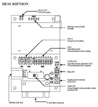
Figure 6.5:�
MB-STD-RS232 � CIRCUIT DESIGN
For more details about this board, refer to Annex A.
Special for STD-402
(Transceiver)
Figure
6.6:� STD-402 Transceiver � CIRCUIT DESIGN
The STD-402 transceiver is an UHF Narrow
Band Multi channel Transceiver.
The UHF
FM-Narrow Band semi-duplex radio data module STD-402 equipped PLL controller in its robust metal housing. Unlike
other transceiver, the STD-402 is
ready to transmit RF data without complicated controller board. The compact
size and low power consumption of the STD-402
make it ideal for battery operated applications where its interference
rejection and practical distance range are much better than similar RF modules
based on Wide Band SAW � resonator frequency devices.
Most of RF
setting are done by internal microcomputer, which allows the user to manipulate
the module without professional knowledge of RF circuit.
Features
�
European EN300 200 standard
compliance.
�
High technology into compact
module for easy operation.
�
Low voltage operation from 3.6
V DC.
�
Low current consumption, ideal
for battery operated applications.
�
9600bps data rate.
�
Carrier sense output for
Multi-Channel access operation.
Application
�
Remote control system.
�
Security systems.
�
Bi-directional communication
systems.
�
Telemetry systems
�
Handy terminal.
STD-402
characteristics
v Common
Communication
form������������������������� Semi-duplex
Frequency
range���������������������� ����������� 433.200 MHz to 433.775 MHz.
Channel
step���������������������������������������� 25
kHz.
Baud
rate���������������������������������������������������������� 9600bps
max.
Supply
voltage������������������������������������ 3.6
� 12 V DC
(Direct Mode).
Dimensions
����������������������������������������� 53
�
35 �
12 mm.
v Transmitter
RF output
power��������������������������� 9 mW �
1mW.
Data input
level����������������������������� 3.6 �
12V (Direct Mode).
Input signal������������������������������������ Digital
Spurious
emission������������������������������������ <
-60 dBm (< 1 GHz).
Supply
current������������������������������������������� 36
mA.
v Receiver
Receiver type���������������������� Double
superheterodyne PLL synthesizer.
Selectivity ��������������������������� � 4
kHz at �6dB point.
Data output ������������������������ Digital.
The STD-402 transceiver has 3 mode
operation guide :
1)��� Direct
Mode Operation Guide (For more details about this mode, refer to Annex B)
2)��� Auto
Mode Operation Guide. (For more details about this mode, refer to�� Annex C)
3)��� Auto
Mode Operation Guide for CPU interface. (For more details about this mode,
refer to Annex D)
Or the MB-STD-RS232 equips STD-402 transceiver module and performs
packet communication using CPU interface mode of the transceiver.
The code
for this program is written in C. The program runs under the Real Time
Operation System (RTOS) VxWorks on the embedded system in the
alternative � LOTTE. The purpose of this program is to get the sensors data
from one serial port and put it on another serial port which is connected to
the transceiver.
The whole C
program code is in Annex H.
The
important thing in this program is the initialization of the serial interface
communication, the following lines contain a description about this
initialization :
� id_com_dev
= open (c_device, O_RDWR ,0);���� (line of code: 17)
This
command is used to open the serial port. When the serial port is not opened,
this function returns �1.
� if
(-1 == ioctl (id_com_dev,FIOBAUDRATE,speed))�������������������� (line of code: 24)
� SerialControl
= (CLOCAL|CREAD);����������������������������������� (line of code: 28)
� Parity
= PARENB ;������������������������������������������������������������������ (line of code: 29)
� CharacterSize
= CS8;��������������������������������������������������������������� (line of code: 30)
� if
(-1 == ioctl (id_com_dev,SIO_HW_OPTS_SET,SerialControl | Parity |��������� CharacterSize))������ ���������������������������������������������������������������� (line of code: 31)
� ioctlvalue
= ioctl (id_com_dev,FIOSETOPTIONS,OPT_TANDEM &~�
����
OPT_MON_TRAP);���������������������������������������������������������������� (line of code: 36)
These
commands initialize the parity, the stop bit, the data length and the
handshaking mode.
The test of the transceiver is shown in following
lines :
1. Connect
the serial cable to the D-SUB 9pin connector.
2. Set
"Cable SW" (Cross / Straight) according to the cable.
3. Connect
the supply voltage of the transceiver to 6V DC.
4. Select
unit to be master and set SW1 to "9" and SW2 to "1". Select
unit to be slave and set
��� SW1 to "9"
and SW2 to "0".
5. Power ON the
units.
6. When
power of the master is turned on, TX, RX and LE LED turn ON and LD blinks.���
��� Radio communication start and continue for
about 10sec.
7. When power of slave unit is turned on, TX, RX
LED turn ON and RSSI turn on when
��� signal from master is received. LD blink
when group setting is completed.
8. After slave unit receives unique module
identification code stored in master units, radio
��� communication can be performed with this
code.
9. Power of the
units.
10. Setting the mode and the property of the
communication by the SW switch.�
�������������������������������� 1
: ON��� ��
Transmitter ����� 1 : OFF �
Receiver
�������������������������������� 2
: OFF� ��� Mode 1
(Two way communication)
�������������������������������� 3
: ON��� ��� Setting
prohibited.
�������������������������������� 4
: ON��� ��� Setting
prohibited.
�������������������������������� 5
: ON��� ��� ACK
response (Yes).
�������������������������������� 6
: ON��� ��� Parity
Yes (Even).
�������������������������������� 7
: ON��� ���
Communication speed.
�������������������������������� 8
: ON��� ���
Communication speed.� (9600bps).
11. MB-STD-RS232
has 64 pre-programmed frequency channels. These frequencies are
����� divided to 8 groups. Each group contains
10 frequencies. The group can be selected by
����� SW2, and the value inside the group is
selected by SW1. The frequency used to built the
����� test is 433.975 MHz. To select this
frequency, set the SW1 switch to 3 and the SW2
����� switch to 1. The master and the slave
unit should be selected to the same frequency.
12. Power on the units.
13. MB-STD-RS232 is in RX mode at wait time (stand
by), which means RX is turned ON at wait time. When the unit receives radio
data from the other unit, the RSSI� LED
turn ON
����� and the unit will start outputting the
data to RS232 port.
14. When the unit get data from PC through RS232C
connector, the data is stored in internal buffer and then will be sent after
the MB-STD-RS232 check that the carrier
frequency to be set is not
used in air. The TX LED turned ON when the unit will transmit the data. The
unit returns to RX mode when all data is gone.
As
described in the implementation in chapter 6, the important things before
testing the user interface program is to take care about the path of the files
that the user interface used, the program run with the user interface, the
initialization of the serial port (number of port, baud rate, parity, data
length, stop bit, handshaking mode, input mode ...), the interval of the timer
used to read data from the receive buffer. If all these commands are done in
the correct way, an EXE file can be made and used.
Connect one
of the transceiver to a PC that contains the user interface program and the
other transceiver to an other PC that contains the program used to send data
(UserInterface_SendData). Then run the two programs and click the Sending_Data
button and the data will be displayed in the user interface program each 500
msec as below :
Figure 7.1:
position & direction of the alternative � LOTTE

Figure 7.3: Status of the
alternative � LOTTE
Figure 7.4: Weather parameters
As we see
in the pictures above that the user interface test with the transceiver test
work very well, and the data are received correctly and putted in their place.
To test the
C program on the embedded system, run the TORNADO 2.0 then the following figure
will be shown :
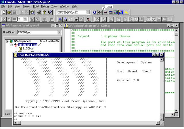
To open the
connection between the TORNADO and the VxWorks machine, open the tools options,
then select "Target server", then "PepVMP", then go to the
list box to select the IP, after that the TORNADO inform you if the connection
is done between it and the VxWorks machine.
So if the
connection is ok, the user will be able to compile the C file, then open a
shell to send commands to the VxWorks machine. Before running the C file on the
VxWorks machine, you should download the C file on it, this thing can be done
by select the project, right click on it and press Download "name of the
project".
If all
thing is done in the right way, the user will be able to type the name of the C
program in the shell (In our project, the name of the C program is
"maincom"), and the data is sent to the serial port of the VxWorks
machine.
The whole
code of the C test program used is shown in Annex G.
Some trouble shooting
|
Phenomena
|
Cause of trouble
|
|
TX-LED blink
|
SW1, 2
setting error. Please check setting of SW1, 2.
|
|
RX_LED blink
|
Low
voltage. Please check supply voltage
|
|
TX and RX
LED blink by turns
|
Internal
EEPROM is something wrong. Please contact us.
|
|
Both RX
and RX LED turn ON
�And no transmission.
|
There
would be interference at set frequency. Please change the frequency. Noise
from PC might be the cause of the problem. Please try to leave the board from
PCs and check it.
|
Frequency CH
setting
There are two frequency settings are available.
�
Fix setting (manual):
Frequency is
set by switches (SW1 & SW2) on the board manually. RSSI-LED indication
helps to set vacant channel.
�
Auto setting:
MB-STD-RS232 search radio carrier to
find vacant channel before starting radio communication and set to vacant
channel automatically. For more details about the frequency table, refer to the
data sheet (page 6,7)
Initial Setting �(Master / Slave)
|
�� SW1
|
���� SW2
|
Function
|
|
���� 9
|
������� 0
|
STD-402
initial setting / set to Slave
|
|
���� 9
|
���� ���1
|
STD-402
initial setting / set to Master
|
|
���� 9
|
������� 9
|
Setting
mode (Lf, Ack, Character strings, etc..) and TEST
|
Operation Mode Setting
SW
|
NO
|
������� Description
|
���������������������� SW3 setting
|
|
����������������� ON
|
����������������� OFF
|
|
�1
|
����� Operation Mode
|
Transmitter
|
Receiver
|
|
�2
|
Mode 2
(One-way communication)
|
Mode 1
(Two-way communication)
|
|
�3
|
(Reserve)
|
Setting
Prohibited
|
Off
|
|
�4
|
(Reserve)
|
Setting
Prohibited
|
Off
|
|
�5
|
� U
� A
� R
� T
|
ACK
response
|
Yes
|
No
|
|
�6
|
Parity
|
Yes (Even)
|
No
|
|
�7
|
Communication
Speed (bps)
|
ON
|
9600
|
OFF
|
4800
|
ON
|
2400
|
OFF
|
1200
|
|
�8
|
ON
|
�ON
|
OFF
|
OFF
|
Stop bit at UART Communication
Normally,
Stop bit is selected one of 1 / 1.5 / 2 bit when COM port of PC
equipment is set-up. When continuous data are outputted, data comes after stop
bit. However there is a case that there is more time space than specified stop
bit length because of asynchronous communication.
The MB-STD-RS232 receives the data from PC
correctly if stop bit is 1 bit or more. Stop bit of data from the MB-STD-RS232 to PC is fixed to 2 bit
therefore communication with PC can be made regardless of stop bit (1, 1.5, 2
bit).
Jumper Setting
There are 6
jumper settings on the board. Changing J4 and J5 can change LED-working
condition to reduce the consumption current.
J1, J2, J3 : Module set up STD-402 434 MHz setting must be Short, Open, Open.
J4: LED operation of TX, RX, RSSI� LED������
Use: Short����� Non Use (off):
Open
J5: LED operation of LD, LE ������������������������������� �����Use: Short����� Non Use(off): Open
J6: CPU reset signal: this must be short
Communication Interface
The board
equips D-SUB 9pin and Modular 6pin as communication interface [8].
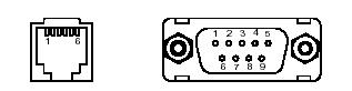
Figure A.1:� Serial Connector
|
Signal
|
I/O
|
Modular
6P
|
������� D-Sub 9p (*)
|
�������������������� Remark
|
|
RD
(RX)
|
I
|
1
|
2
|
3
|
Input
terminal / from PC
|
|
RS
(RTS)
|
O
|
2
|
7
|
8
|
Hi when the
equipment become data reception possible.
Lo when
internal
Buffer
is full
|
|
SD
(TX)
|
I
|
3
|
3
|
2
|
Data
output terminal / from PC
|
|
CS
(CTS)
|
O
|
4
|
8
|
7
|
Hi when SD
terminal send data
Lo when SD
terminal do not send data
|
|
GND
(SG)
DC
(+)
|
5
|
��������������� 5
|
GND
|
|
6
|
��������������� -
|
Supply power (DC 4 to 9V) is
possible
From
Modular 6pin.
|
Communication Cable
Cross
cable which mainly connect between PCs and straight cable which connect PCs and
peripheral RS 232 equipment are available as RS 232 standard cable. Please set
�Cable SW� (Cross / Straight) according to the cable. For more details ,refer
to the Data Sheet (page 11,12).
Operation Mode
MB-STD-RS232 has two operation modes as below :
�
�
Operation Mode 1:����� Two-way (Semi-duplex) communication
�
Operation Mode 2:������ One-way communication
� Operation Mode 1: Two-way
(Semi-duplex) communication
This mode
is useful for an application of two-way communication with the Ack/Nck
Response
between PC and RS232 equipment, and an application that returns the data from
RS232 equipment to PC according to the command from PC MB-STD-RS232 is in RX at wait time (stand by). When the unit
receives radio data from the other unit, the unit will start outputting the data
to RS232 port. When MB-STD-RS232 get
the data from PC through RS232C connector, the data is stored in internal
buffer and then will be sent after the
MB-STD-RS232 check that the carrier frequency to be set is not used on air.
The unit returns to RX when all data in buffer is gone.
1:N communication is possible by implementing the
group setting. In this case, the application software have to be programmed to
consider that identification number of RS232 equipment have to be included in
transmission command, and only the equipment which has requested ID number
returns the data when its command is received. In this operation mode, Only Fix
CH setting can be used.
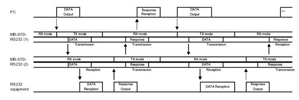
Figure A.2: Two-way,
Semi-Duplex Communication
� Operation Mode 2: One-way
communication
This mode
is useful for an application of one-way communication from PC to measurement
equipment. TX (transmitter) / RX (receiver) setting can be done with dip switch
on the MB-STD-RS232. TX unit
transmit the signal at selected channel regardless that data is in buffer or
not. RX unit outputs the data to RS232 port when radio signal is received. (RX
unit does not transmit even data is imputed to RS232 port).
1:N communication is possible by implementing the
group setting. 1 * TX unit to N * RX units communication is possible.
In this
operation mode, Either Fix channel setting or Auto channel setting is used.
In Auto
setting, TX unit perform automatic RF channel search and transmit the data in
the vacant RF channel. RX unit perform channel scan to detect transmission
signal and set to the RF channel.
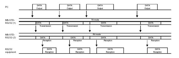
Figure A.3: One-way Communication
Restriction
on data communication
The MB-STD-RS232
equips STD-402 transceiver module
and performs packet communication using CPU interface mode (data length 63bit)
of the transceiver.
Serial data or command stream from PC or other
equipment connected to the MB-STD-RS232
is pocketed and sent to a receiver. When these data are outputted from the
unit, the time space appear as shown below. The time space (delay) is 300msec
or more when operation mode 2 (One-way communication) is used.
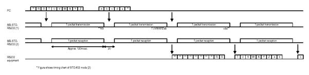
Figure A.4: Data Communication
ACK Auto
Response Function
Depending on RS232 equipment, but some equipment stop
or become error and repeat transmitting same data if Ack/Nck command is not
returned as response signal within several 10msec.
This is not problem in wired communication because PC
can return Ack/Nck command immediately after receiving data from RS232
equipment. Wireless communication with the MB-STD-RS232
have a few second time-lag for the response. This function is given to avoid
error caused by such situation. It is realized
to return Ack (or specific response string) response return.
- MB-STD-RS232 operates as that the
data from RS232 equipment is suppose to carry delimiter symbol (Etx, Lf
etc�) at end.
- When Ack/Nck character is
contained in output from RS232 equipment, MB-STD-RS232 judges that the Ack/Nck character is the response
from PC and when it is not contained the output is recognized as data
stream (i.e. measurement data) for request
����� data command from PC. The MB-STD-RS232 sends Ack response only if
this data�
����� stream (without Ack/Nck) is recognized. ��������
����������� (If
there is data in TX buffer, the Ack will be sent after that).
- Delimiter, Ack/Nck and
character string to recognize these operation can be changed by user.
Example
�������������������� Delimiter ������������������������������������������ �Lf�
(0AH)
���������������������������������� Response
detect code������������������� 1��������� �Ack� (06H)
��������������������������������������������������������������������������������� 2��������� �Nck������������ (15H)
����������������������� Auto response character
string����������� �Ack CR Lf�� (06 0D 0AH)�
Max. 16 characters
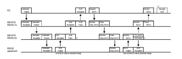
Figure
A.5: ACK Auto Response
Group Setting
The MB-STD-RS232
has stored unique module identification number in the radio module. When one
unit is set up for master and other unit(s) is for slave, slave modem unit
operate with same ID as master unit.
If this setting (group setting) have not finished,
radio communication between the MB-STD-RS232
is not possible even with same frequency.
� Setting Procedure
- Select unit to
be master and set SW1 to �9� and SW2 to �1�. Select unit(s) to be slave
and set SW1 to �9� and SW2 to �0�. Power on the units.
- When power of
the master unit is turned on, TX, RX and LE LED turn ON and LD LED blinks.
Radio transmission start and continue for about 10sec.
- When power of
slave unit(s) is turned on, TX, RX LED turn ON and RSSI turn ON when
signal from master is received. LD blink when group setting is completed.
After slave
unit receives unique module identification code stored in master units, radio
communication can be performed with this code.
Note:
This setting is to set identification code for radio communication. Original
unique module identification code of slave unit itself remains unchanged. When
the unit was used for slave is set to
master and
perform communication, identification number is different from former
communication. Therefore interface does not occur.
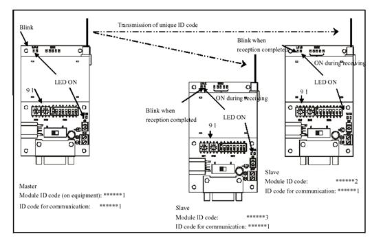
Figure A.6: Master
& Slave Units
Ack Auto
Response Setting
Delimiter,
Ack/Nck code and auto response character string (max. 16 characters) for
recognition of Ack auto response can be changed from RS232 port using software like
Windows Hyper Terminal.
� Procedure
1.
Connect MB-STD-RS232 and PC with RS232 cable. Set SW1 and SW2 on the MB-STD-RS232 to �9�, �9�, then power
ON.
2. Start
up the Hyper Terminal and set communication condition as below.
�������������������������������� � 4800bps, Bit = 7, Parity = Odd, Stop Bit = 1,
Flow control = Hard ware.
3. At
first, type �/A CrLf� and return. Check if the MB-STD-RS232 modern return the product name and program version.
4.
Set up with reference to the
following table.
|
Command
|
Transmission format
|
��
Correct Response
���� ��Data (example)
|
�������
Description
|
|
�����
�/A�
|
��������
�/A CrLf�
|
�/A MB-STD-RS232,����������
�
001.000 CrLf�
|
Product name, Program ver.
|
|
�����
�/I�
|
��� �/I
06, 0D, 0A CrLf�
|
�Ok CrLf�
|
Set and check of Ack response character������������ sting (HEX)
Max. 12 character (prohibit to�� include������������� ASCII code �00�)
|
|
���������
�/I CrLf�
|
�/I 06, 0D, 0A CrLf�
|
|
������
�/K�
|
�������
�/K 06 CrLf�
|
�OK CrLf�
|
Set and check of Ack response detect�������������������� code 1 (HEX).
Example : 06H = Ack
|
|
��������
�/K CrLf�
|
�/K 06 CrLf�
|
|
������
�/L�
|
�������
�/L 15 CrLf�
|
�/L OK CrLf�
|
Set and check of Ack response detect���������������� code 2 (HEX).
Example : 15H = Nck
|
|
��������
�/L CrLf�
|
�/L 15 CrLf�
|
|
������
�/M�
|
������
�/M 0A CrLf�
|
�OK CrLf�
|
Set and check of delimiter (HEX)�������
Example : 0AH = Lf
|
|
��������
�/M CrLf�
|
�/M 0A CrLf�
|
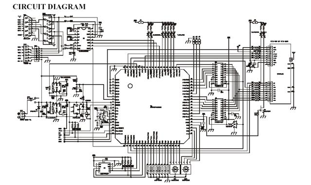
Circuit
diagram for the MB-STD-RS232
� STD-402� [Direct Mode Operation Guide]
General
Description
The STD-402
is a short range device stipulated by CEPT/ERC recommendation 70-03 and is a
radio module complying with ETSI standard EN300-220-1 with a transceiver built
into its compact case.
The built-in PLL synthesizer
circuit enables both transmission and receipt through 64 pre-set channel
frequencies between the 433 to 434 MHz bands.
The transmit mode / receive mode settings and the
frequency channel settings can be made easily with dip switches or jumpers
without the use of an external microcomputer.
As the system operates on low voltage and low current
consumption in consideration of mobile communications, battery operation is
also possible.
The FSK modulation enables transmission at a maximum
of 9,600bps. Also, when multiple channels are to be used simultaneous or if
high communication standards are required, the
MSK modulation enables transmission at a maximum of
2,400bps. However, it is necessary to install an MSK modem IC externally for
this purpose.
The radio module has been designed with high levels of
reliability cultivated through long-term results, and this provides excellent
levels of selectivity receiving sensitivity and radio interference
capabilities.
Features
�
Comply with EN 300 220
�
Compact size (53mm * 35mm *
12mm) with built-in transceiving functions (STD-402)
�
Baud rate of maximum 9,600bps
�
Simple channel setting with
switches
�
Continual �0� or �1� data
transmission for a maximum of 20msec.
�
High-level endurance
capabilities against the effects of antenna reflection and surrounding
equipment
�
Low-voltage operations : 3.6 V
to 12 V
�
Low-current consumption : 36mA
(transmit mode), 26mA (receive mode)
Applications
v Telecommand
and Telecontrol
v Telemetry
v Alarms
v Data
terminals
Pin description
|
Number
|
Pin Name
|
I/O
|
������� Description
|
����� Equivalent circuit
|
|
� ���1
|
�� CAR
(STATUS)
|
� O
|
Carrier
sense output of the receiver.
The RSSI
signal (receiving level)
Will become
�H� when the signal���� exceed the
threshold.
|
|
|
���� 2
|
��� RSS
����
|
� O
|
The
receiving level output of the���
receiver. The strength of the RF��������� level is converted to the
direct�������� current voltage.
|
|
|
���� 3
|
����� AF
|
� O
|
The AF
output of the receiving������� section.
|
|
|
���� 4
|
����� DO
|
� O
|
The data
output for the receiving���������
section. The port uses FET buffer�
����output, the �H� level is
Vcc.
|
|
|
���� 5
|
����� T/R
|
� I
|
TX(transmit
mode) / RX (receive������ mode)
setting. The port is pulled�����������������
up with resistor.
TX mode: L
(GND)
RX mode: H
(Open)
|
|
|
���� 6
|
������ DI
|
� I
|
Data input
for the transmission������ section. The
port uses transistor�������� input, the
digital �H� level is Vcc����������� and
the digital �L� is GND.
|
|
|
���� 7
|
���� VCC
|
� -
|
The power
supply terminal.
Operates on
3.5V to 12V, but the�������������� same
Vcc level as the surrounding���������������
circuits must be used.
|
|
|
���� 8
|
����� GND
|
� -
|
The ground.
Extend
the pattern over the widest������� area
possible on the printed circuit���������������
board.
|
|
|
���� 9
|
����� LD
|
�O
|
� The LOAD signal output for���������������
External parallel -> serial register
� The RESET signal is output with��������������
��� The receive mode.
� The port uses FET buffer output,��������������� the �H� level is Vcc.
|
|
|
���� 10
|
����� LE
|
�I/O
|
� The LATCH ENABLE signal�������������������������������������� �������������������������������������������output
for external serial ->
Parallel register.
� �Setting mode switch input.
|
|
|
���� 11
|
��� RDY
�� (CLK)
|
�O
|
�The READY signal output. RDY is�����������������������������������
�Active when at �L�. The following������������
�Conditions apply when RDY is �H�.���������������
(1) Initial status.
(2) CAR is �H�
Call name
being transmitted.
|
|
|
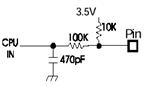 ���� 12 ���� 12
���� 13
���� 14
���� 15
���� 16
���� 17
|
��� CH5
��� CH4
��� CH3
��� CH2
��� CH1
��� CH0
|
� I
|
� Set the various conditions when �����������������in the setting mode.
� Sets the ID address with normal������������ operations. 63 address
types����������������� between 1 and 63
are available.
� Pulls up each port.
|
|
Electrical characteristics
�
Common characteristics
|
�������������� Item
|
������������� Rating
|
��� Conditions/remarks
|
|
Communication
form
|
Semi-duplex
|
|
|
Modulation
|
F1D
|
FSK
|
|
Oscillation
system
|
PLL
controlled VCO
|
|
|
Frequency
range
|
433.200 �
434.775 MHz
|
|
|
Channel
step
|
25 kHz
|
|
|
Number of
RF channel
|
64 channels
|
|
|
Baud rate
|
4800,� 9600bps
|
FSK
|
|
Modulation
polarity
|
Positive
|
|
|
Demodulation
polarity
|
Positive
|
|
|
Antenna
impedance
|
50 Ohm
|
|
|
1st IF
|
21.7 MHz
|
|
|
2nd
IF
|
450 kHz
|
|
|
Range
|
200m or
more
|
F1D 9600bps
|
|
Operation
temperature
|
-10 to 55�C
|
|
|
Operation
power voltage
|
3.6 � 5V
|
|
|
Supply
current
|
36mA
|
TX mode
|
|
26mA
|
RX mode
|
|
Dimensions
|
53*35*12mm
|
|
|
Weight
|
34g
|
|
�
Transmission section
characteristics
|
�������������� Item
|
��������
Rating
|
����������
Conditions
|
|
Transmitter type
|
PLL synthesizer
|
|
|
RF output power
|
9.0mW � 1.0mW
|
10mW
|
|
Frequency stability
|
� 4ppm
|
-10 to + 55�C
|
|
Spurious emission
|
< -60dBm
|
< 1GHz
|
|
< -50dBm
|
> 1GHz
|
|
Deviation
|
�1.9 to 2.1 kHz
|
*1
|
|
S/N ratio
|
> 25dB
|
*1
|
|
Adjacent channel power
|
> 40dB
|
Spectrum analyzer act. *1
|
|
Carrier sense level
|
-107 dBm
|
Fixed
|
|
Transmitter start-up time
|
< 30msec
|
PLL data setting
|
|
Channel switching time
|
< 15msec
|
25KHz
|
|
< 30msec
|
100KHz
|
*1:
9,600bps, 511 bit (Pseudo Noise)
�
Receiving section
characteristics
|
���������������� Item
|
������������� Rating
|
Conditions
|
|
Receiver
mode
|
Double
super heterodyne
|
|
|
Sensitivity
|
< -117
dBm
|
25�C,� *2
|
|
Spurious
response
|
> 45dB
|
*3
|
|
Selectivity
|
> 45dB
|
*3
|
|
Local
frequency stability
|
� 4ppm
|
-10 to +55�C
|
|
Radiation
from local oscillator
|
< -65
dBm
|
< 1GHz
|
|
< -60
dBm
|
> 1GHz
|
|
Output
level
|
350m Vp-p
|
100Kohms
terminate *4
|
|
Carrier
sense level
|
-113 dBm
|
Fixed
|
|
Carrier
sense response time
|
< 30msec
|
PLL data
setting
|
|
Channel
switching time
|
< 15msec
|
25KHz
|
|
< 25msec
|
100KHz
|
|
Bit error
rate
|
1 �
10^-2
|
Less than
�110dBm
|
|
1 �
10^-4
|
Less than
�107dBm
|
*2: AF = 1KHz, fmod = 2KHz, CCITT filter ON
*3:
Jamming waves AF = 400Hz, fmod = 40%
*4:
Dev:= 2Khz, AF = 1KHz
*5:
256bit / 4800bps
Modes
The STD-402 can be controlled manually with
a simple set of external switches and jumpers, or with microcomputer
controller.
Figure B.1:� Models
& Modes
Modulation mode
�
The maximum baud rate is
9,600bps with FSK. The data format may be decided by the user.
�
The MSK modulation is
recommended when stable operations are required during the use of multiple
channels within the same area. However, the MSK mode requires an external MSK
modem IC (MSM6882 manufactured by OKI or an equivalent model). Restrictions in
the performance of this IC mean that the maximum baud rate is 2,400bps.
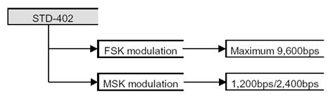
Figure B.2:�
Modulation Mode
For more details about the channel table and the
Manual Mode, refer to Data Sheet (page 2...18).
Transceiver
mode with microcomputer
�
Connection method
� More
complex settings are made available when the STD-402
�modes and channels are controlled by
microcomputer.
� By
developing microcomputer software that monitors the STD-402� READY ports, it is possible to avoid
channels already occupied by
�other radios in the same way as MCA
(Multi-Channel Access) and
�automatically set up empty channels.���������
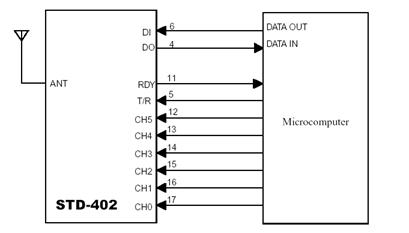
Figure
B.3:� Connection Method
Timing for
transmit mode setting
�
The flow chart and timing
chart for transmit mode setting when under microcomputer control are provided
below.
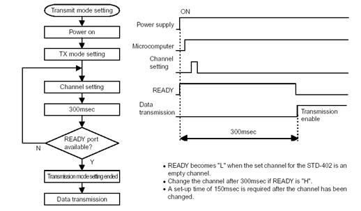
Figure
B.4:� Timing for transmit mode setting
Timing for
receiving mode setting
�
The flow chart and timing
chart for receive mode setting when under microcomputer control are provided
below.
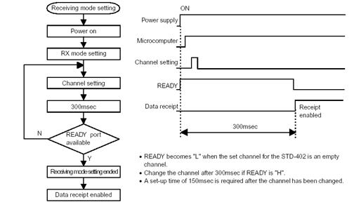
Figure B.5:� Timing for receiving Mode
MSK Modulation mode
� Modem IC
� The
MSM6882 MSK modem IC manufactured by OKI is�
recommended for the MSK (Minimum Shift Keying) modulation mode.
� Modulation
MSK waves are emitted by loading transmission data into
�the
encoder.
� The
decoder converts MSK waves into receiving data.
� Examples
for the application of the MSM6882 terminal function, the
�transmission mode and the receiving mode are
provided in the Data���
�Sheet. For more details, refer to STD-402
Direct Mode Operation Guide (page 21, 22, 23)
Cautions
�
Power supply
� The
operating voltage range for the STD-402
is between 3.6V and 12.0V.
�A voltage
exceeding the maximum of 12.0V will result in damage to the
�device.
� Ensure
that an open drain or open collector port is connected when the
�TX/RX, CH0
to CH5 and external circuits are connected together.
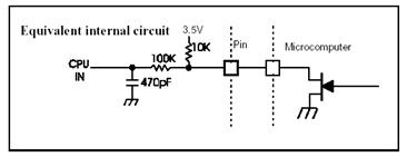
Figure B.6:� Power Supply
�
Reverse connection protection
circuit
v When
using low-voltage with battery operations
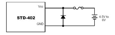
Figure B.7:� Protection Circuit
�
As the maximum battery supply
current will flow into the diode
��� when the battery is connected in the
reverse position, much
��� consideration must be given to the PC (heat
loss) in the diode.
�
Although this method is the
simplest, long-term heat emission
��� may result in the outbreak of fire. Take
extreme caution when
��� handling this.
v When
using high-voltage mains power for stable operations
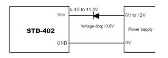
Figure B.8: High Power
�
Although this method will not
result in the buildup of heat in the
��� diode, it will result in a lowering of the
forward voltage in the
��� diode and the efficiency rate of the mains
power will be lower
��� with batteries and other low voltages.
�
The forward voltage will
differ depending on the type of the
��� diode, but the general rectification is
approximately 0.6 to 0.7V.
Antenna
v Antenna
and radial
�
the STD-402 antenna is approximately 17cm with a one quarter wavelength
in the 434MHz band. The unit�s metal case not
only acts as the ground but is also known as the radial to radiate the
electronic radio waves from the antenna and radial. The phase is in inverted
with the redial and antenna.
�
Increase the module�s ground pattern as
much as possible. The electronic wave radiating power is strongest at the tip
of the antenna, and when brought close to the unit�s case, or radial, will work
to cancel each other out, causing dramatic effect to the arrival distance.
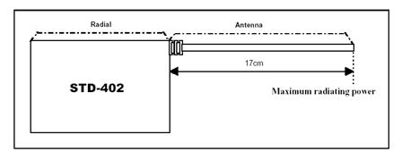
Figure B.9: Antenna
v Incorporating
into equipment
�
A direct line is ideal for the
antenna, but it should be separated from the case as much as possible when
space for incorporating it into the equipment is limited.
Measured data
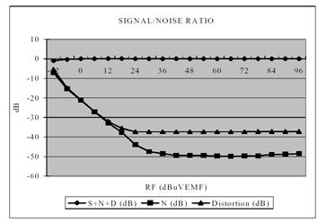
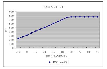
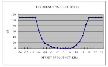
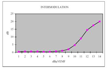
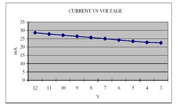 �
�
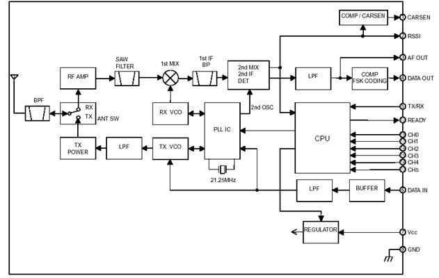
The STD-402
auto mode is a operation mode that is equipped with automatic link function and
an encoding/decoding function. Automatic link searches vacant channels in order
to use forty six channel frequencies without hindrance or interference. The
encoding/decoding function establishes an interface between the data I/O
circuit and radio assembly and executes the necessary communication protocols.
The transmitter�s
input circuit and the receiver�s output
circuit can easily be connected together with a general-purpose IC.
Note: The STD-402
auto mode supports only one-way communication (uni-directional) transmissions
(transmitter -> receiver) but support for simplex communications
(bi-directional) is planned for the future.
�
The automatic link function
automatically connects to channels that do not cause interference.
�
Simple I/O circuits with the
built-in encoder/decoder.
�
The I/O connections can be
expanded to a maximum of 63 bytes
�
The built-in micro-computer
greatly reduces the cost of new development.
�
Perfect for combining with
other equipment.
� One-way
system
v Tele-control
�
For controlling cranes,
concrete pump vehicles, golf carts, remote opening/closing for various
purposes, traffic lights for road works, etc...
Support for the following applications is planned for
the future.
� Simplex
systems
v Data
transmission
�
Handy terminals, bar-code
readers
v Security
�
Transmission of anti-theft
alarms, immobilizes for cash delivery trucks, notification of customers
entering retail shops, etc.....
v Telemeter
�
Water level monitoring for
canals and dams, etc..., monitoring of various alarms, etc... .
�
The auto mode automates
numerous functions with the use of the built-in micro-computer.
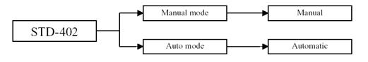
Figure C.1: Configuration
�
The features of both modes are
shown in the table below
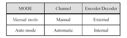

Figure C.2: Mode
Explanation for internal
processes (1) [Automatic channel search]
�
the automatic channel search
is a system that detects the carrier level of the channel in use to search for
vacant channels in order to avoid interference with other radios. This is
controlled automatically by the built-in micro-computer.
�
The channel search is executed
by the module from the pre-determined starting channel.
�
For example, if the channel search
was executed from [0ch], the procedure would be as follows :
1.
The STD-402 is set in the receiving mode.
2.
Set as channel 0 (433.200MHz)
3.
The carrier level is detect
and compared with the standard level
4.
If the channel is occupied,
the frequency is increased by two channels (50KHz).
5.
If the channel is vacant, the
system is switched across to the transmission mode.
6.
The vacant channel is set.
7.
Transmission is started.
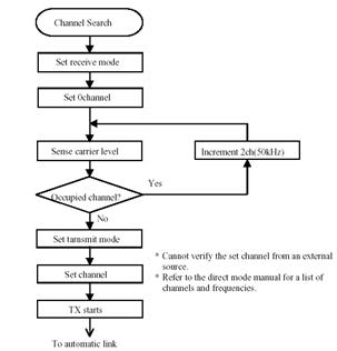
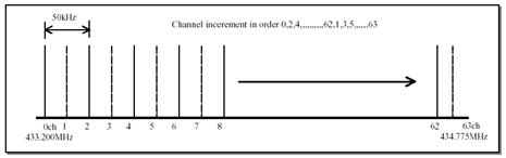
Figure
C.3: Automatic Channel Search
Explanation for internal
processes (2) [Automatic link]
�
This is controlled
automatically by the built-in micro-computer in the same way as the automatic
channel search.
�
All modules are started from
[0ch] in the case of the automatic link.
�
The channel search is executed
by the module from the pre-determined starting channel.
�
For example, if the channel
search was executed from [0ch], the procedure would be as follows :
1.
The transmitter set for the
vacant channel commences transmission.
2.
The receiver is set at channel
0 (433.200MHz).
3.
The carrier level is detected
and compared with the reference level.
*�� the reference level is different for the
transmitter and receiver.
4.
If it is below the standard
level, the frequency is increased by one channel (25KHz).
*� Increased by two channels for transmitter,
but only one channel for the receiver.
5.
The ID data is received and
compared with the ID register.
6.
Increased by one channel
(25KHz) if the ID number matches.
7.
Switched across to the
communication mode if the ID number matches.
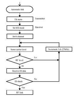
Figure
C.4: Automatic Link
Explanation for internal
processes (3) [ID number registration]
�
It is necessary to register an
ID number for the transmitter and receiver in order to enable the STD-402 to establish an automatic link
between two devices.
�
If the transmission is
performed on the same frequency from another radio or an STD-402 with a different ID number, the receiver will continue to
search the channels until it finds an ID number that matches its own.
�
The serial number is unique
number set in the factory at the time of shipment and can only be read.
�
The ID register is a register
for storing the ID number.
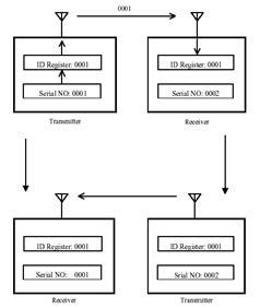
Figure
C.5: ID Number Registration
�
As shown above, the number
registered in the ID register remains the same even when switching between the
transmitter and receiver, so it is not necessary to register a new ID number.
Explanation for internal
processes (4) [Encoder]
� Connection method
�
The illustration below shows
the basic circuit when the STD-402
is used in the TX mode (transmitter).
�
The 74HC165 is a
general-purpose 8-bit parallel input -> serial output converter.
�
The STD-402 detects disconnection, so ensure that a DO is connected to
the SI.
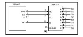
Figure
C.6: Encoder
� Timing chart
�
The timing for the STD-402 TX mode is shown below.
�
The micro-computer built into
the STD-402 is equipped with an
encoding function and communication protocols to convert the automatic link ID
numbers, the various control data and the transmitted data into FSK data.
�
The entire data is called as a
�frame�, and the
transmission data is inserted once into a single frame. The data is transmitted
continually until the power supply is switched off.
�
The length of the control data
is fixed, but the transmission data can be changed between 1 byte to a maximum
of 63 bytes in accordance with the application.
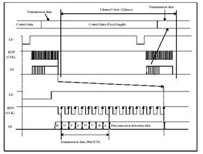
Figure C.7: Timing chart for
STD-402 TX mode
(1)
The parallel data is latched
onto the clock asynchronously when the LD signal is �L�
(2)
Serial data is shifted at the
RDY (clock) rises when the LD signals is �H�.
Explanation for internal
processes (5) [Decoder]
� Connection method
�
The illustration below shows
the basic circuit when the STD-402
is used in the RX mode (receiver).
�
The 74HC595 is a
general-purpose serial input -> 8-bit parallel output converter.
�
The STD-402 detects disconnection, so ensure that a QH is connected to
the DI.
�
The 74HC595 latch data is
cleared when LD is �L�
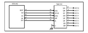
Figure
C.8: Decoder
� Timing chart
�
The timing for the STD-402 RX mode is shown below.
�
The micro-computer built into
the STD-402 is equipped with a
decoding function and communication protocols to convert the received FSK data
into control data and the transmitted data (serial data).
�
The transmission data is
output once into a single frame. The data is received continually until the
power supply is switched off.
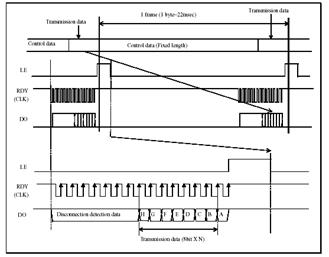
Figure
C.9: Timing chart for STD-402 RX mode
(1)
The serial data is shifted
when the RDY (clock) rises.
(2)
The parallel data is latched
onto the clock asynchronously when the LE signal rises.
Explanation for internal
processes (6) [Data format]
� Communication data format
�
The STD-402 control data is of fixed length and comes in a unique
format that includes the ID code for radio links and special codes.
�
The user data (transmission
data, receiving data) is between 1 byte and 63 bytes depending on the number of
I/O connections, and the transmission time will be extended in accordance with
the length of the transmission data.
�
The communication data format
is shown below.
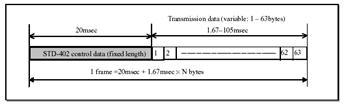
Figure
C.10: Data Format
� Transmitting data between
Transmitter and receiver
�
The communication data is
transmitted continually during transmission. However, the transmission data
will not actually travel continuously at 4,800bps owing to the fact that the
control data is transmitted by frame by the encoder.
�
Using 1 byte of data as an example,
the data volume (number of bytes) transmitted within a one-second period is as
follows.
D
= 1000msec �
{20msec + (1.67msec �
1)} �
46 bytes.
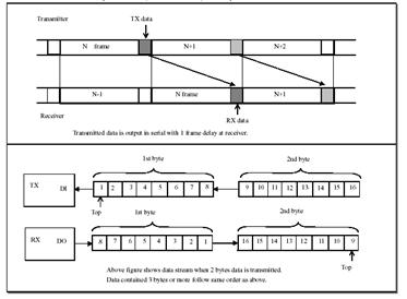
Figure C.11: Transmitting Data
between TX and RX
For more details about the Encoder/Decoder and the
setting� mode, refer to Data Sheet (page
13...19)
Communication
mode
�
the communication mode enters
normal operation when the power supply is switched on after all transceiver
settings have been made in the setting mode.
�
First of all with the
communications mode, a link is established with the transmitter and receiver
with the same ID number in accordance with the procedure explained for the
automatic link, and data transmission is then started.
�
Once a link has been
established, communication will be carried out on the same channel unless the
power supply is switched off.
Local ID
numbers
�
It is possible to transmit the
data from one transmitter to a maximum of 63 different receivers with the STD-402 auto mode.
�
Local ID numbers must be set
for each of the receivers for identification purposes. The ID numbers are set
with the CH0 to CH5 ports.
�
The (LD = L) reset signal is
output and the data is cleared under normal conditions when the ID number of
the transmitter and receiver do not match. [LD] is invalidated and the
receiving data is output if the ID numbers do match. However, if the ID number
for the data and clock matches, it is output regardless of the local ID.
�
If the ID number for the
transmitter is [0 (ALL)], the receiver will output the data regardless the ID
number.
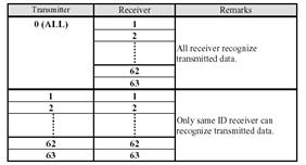
Figure
C.12: Local ID Numbers
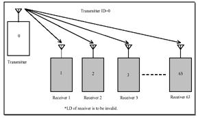
Figure C.13:
Communication 1:N

Figure
C.14: Communication 1:1
To see the ID address table, refer to Data Sheet (page
22).
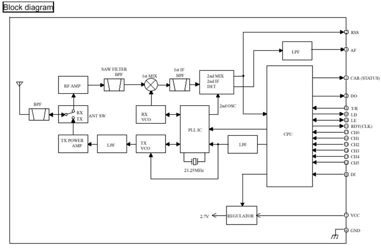
� STD-402
[Auto Mode Operation Guide for CPU Interface]
Or the board used to equips
the STD-402 is the MB-STD-RS232, so
the� this mode (Auto Mode Operation Guide
for CPU Interface) is used like mode of the STD-402 transceiver.
Auto mode :
CPU interface conceptual illustration
� Wired Communication
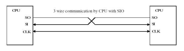
Figure D.1: Wired Communication
Above image shows basic construction of data
communication with SIO (Synchronous Serial Input Output)
� Radio Communication through
STD-402 Auto mode
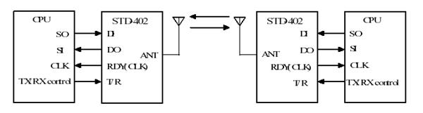
Figure D.2: Radio
Communication
Above figure
shows the communication that replaces the wire with the radio module (STD-402). Radio communication is not
stable as wired communication.
In
addition, the procedure in the beginning of radio communication link
(connection between transmitter and receiver), TX/RX switching and the
disconnection of radio communication are unique for radio communication
therefore specific protocol is required for radio communication.
STD-402
auto mode provides such specific protocol as the function of radio link,
frequency channel selection and encode/decode.
Transmission concept
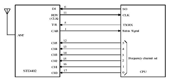
Figure D.3: Transmission Concept
Data
from SO (Serial Output) of CPU, which is shifted on the raising edge of clock
signal is imputed to DI (Data Input) of STD-402.
User data can be set with any data size in byte from 1-63 byte. STD-402 internal CPU adds
identification code, error correction code and other internal process code and
then transmit them as modulation data in frame.
Reception concept
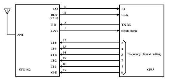
Figure D.4: Reception Concept
When
the receiver receives data of which ID code, error correction and code and
other internal process code are matched, only user data is outputted from DO by
byte in synchronism on the rising edge of clock. If no signal is received or
any of ID code, error correction or other process code is not matched, CLK and
data signal does not appear.
Connection
between STD-402 and CPU
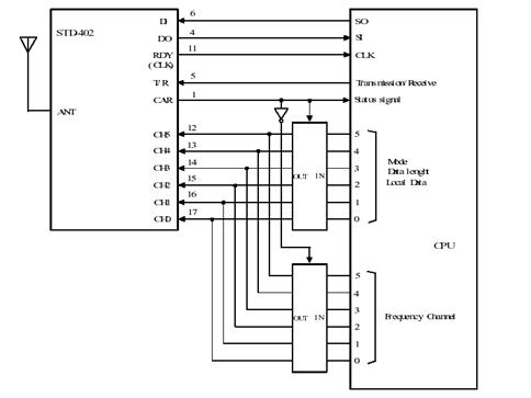
Figure D.5: Connection between STD-402 &
CPU
STD-402
Terminal Description
|
Terminal
|
Description
|
|
DI
|
Transmission data input terminal
Connect to SO (Serial Output) of CPU
|
|
DO
|
Receive data terminal
Connect to SI (Serial Input) of CPU
|
|
RDY (CLK)
|
Shift clock output for SO and SI serial data
|
|
T/R
|
Transmitter/Receiver function select terminal
L: TX,�����������
H: RX
|
|
CAR
|
Status signal for transmission/receive and multiplex
switching signal for CH0-5. The port shows L when TX and H when RX.
Multiplex switching signal comes at end of frame. It
can be used for frame status signal.
|
|
CH0 � 5
|
Input ports for Mode & data rate, frequency
channel selection mode (Auto/Fix) and data length (1 � 63 byte) for initial
setting.
Input port for local ID (0 � 63) and frequency
channel (0 � 64 channel) during normal operation.
|
Communication
Protocol
9.1
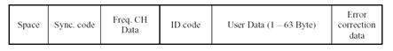
Figure
D.6: Communication Protocol
STD-402
communication data format is shown as above. STD-402 internal CPU will make above data automatically except User
data. Data connection is possible by feeding user data (1 � 63 bytes) to 3 wire
SIO ports of CPU in synchronism with CLK.
In each frame, STD-402
�process the data internally and
Input/Output user data. In general, data is sent and received as �packet�.
Initial
Setting
Initial setting configures STD-402 internal setting.
1.
MODE
� Direct
mode
� Auto
mode: (Logic interface)
� Auto
mode: CPU interface
2.
FREQUENCY CH (channel)
� Auto
channel mode STD-402 automatically
search vacant channel and make radio link.
� Fixed
channel mode � Set frequency channel to 0 � 63 channel.
3.
DATA LENGTH
� User
data length per frame (1 to 63 byte)
Setting to transmitter (master) and receiver (slave)
is different. MODE is set to both transmitter (master) / receiver (slave).
FREQUENCY CH and DATA LENGTH are firstly set to transmitter (master) then these
data are transmitted to receiver (slave) and then the receiver (slave) memorizes
the data.
Above three setting data (MODE, FREQUENCY CH and DATA
LENGTH) are inputted to CH0 � 5. MODE and FREQUENCY CH data are inputted to the
ports in multiplex process, and DATA LENGTH data are inputted from the port for
Mode in sequence.
Initial setting process will start with LE port �L� at
power ON and complete with LE port �H�. In normal operation, power supply of
the module must turn ON with LE port �H�.
It is recommended to use regulator with controller
terminal for STD-402 power supply
control.
Completion of initial setting can be confirmed with LD
port output.
For more details about setting parameter, refer to
Data Sheet (page 9)
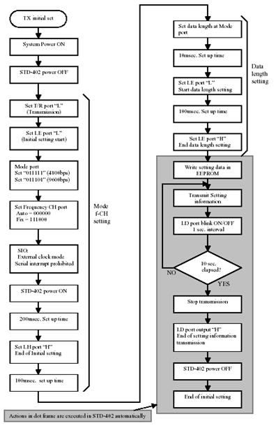
Figure D.7: TX Initial Setting
Flow chart
Receiver : Initial setting flow chart
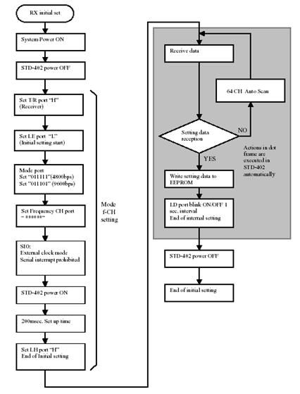
Figure
D.8: RX Initial Setting Flow chart
Normal
Operation
Local
ID and Frequency CH can be set at CH0 � 5 in Normal
operation.
- Local ID
Set Local ID
(0 to 63)
- Frequency CH
Fixed channel
mode (0 to 63 CH)
� In
normal operation, CLK will be outputted when STD-402 internal set-up is completed and data communication is
ready after power ON, TX/RX switch and frequency CH change. CPU needs to check
interruption.
� Set
up and communication link between TX and RX. �����������������������������������Approximately
10msec of frequency setting time is needed because STD-402 uses a synthesizer system. Also, demodulation circuit in the
receiver work in AC
������
operation, DC drift occurs specially when power is supplied. Thus,
RF��������
communication is not stabilized
during approx. First 100msec. It is therefore recommended to send dummy data
(example 00H) few times before sending actual data.
� Carrier
Sense
STD-402
performs carrier sense function to check the set channel is busy or vacant.
When module is set fixed channel mode and the set channel is occupied, a clock
is not outputted from STD-402. In
this case, please wait for interruption or change the other frequency channel.
Transmitter: Timing at power ON
� Following
shows transmitter timing chart at the time of STD-402 power supply ON. Set to T/R port to �L� (transmit).
� Transmission
cycle of data is defined as frame. Following timing figure shows one byte
transmission. It can be set any byte from 1 to 63 bytes. Time of 1 frame is (20
+ the number of byte * 1.7) msec.
� Data
transmission is not possible during module setting time (240msec). It is
recommended to send 1 to 5 frame dummy data (example 00H) at the beginning of
transmission to help initial radio communication link.
� T/R
port, frequency CH and local ID data will be read at the end of frame.
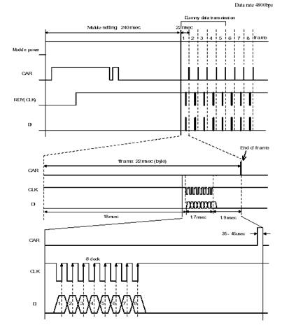
Figure
D.9: TX, Timing at power ON
Transmitter:
Flow chart at power ON
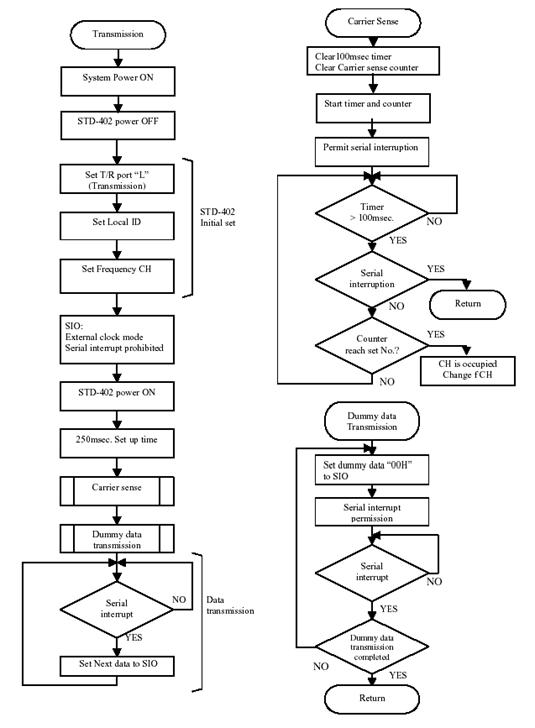
Figure
D.10: TX, Flow chart at power ON
Receiver:
Timing at power ON
Following
shows Receiver timing chart at the time of STD-402
power supply ON. Set T/R port to �H� (Receiver).
� Receiving
cycle of data is defined as frame. Following timing figure shows one byte
transmission. It can be set any byte from 1 to 63 bytes. Time of 1 frame is (20
+ the number of byte * 1.7) msec.
� Data
can not be received during module setting (approx. 165 msec).
� T/R
port, Frequency CH, and Local ID data will be read at the end of frame.
� Following
shows timing that receiver turns ON when radio signal from transmitter has been
transmitted.
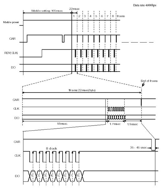
Figure
D.11: RX, Timing at Power ON
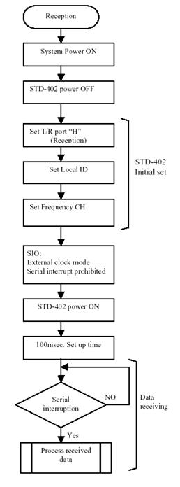
Figure
D.12: RX, Flow chart at Power
ON
Transmitter:
Frequency channel change timing
Following
shows timing chart at time when the transmitter frequency channel is changed
from 7 to 39 channel.
� Channel
data will be read at the end of frame and the data will be set at next frame.
If channel data is changed at 1 msec or later after final clock (CLK), the data
will be read at next frame.
� The
figure shows the example that data size is one byte. Data will be read by 22
msec span.
� Data
transmission is not possible during channel switching and setting period
(approx. 210 msec.). The channel switching time is same at any channel set.
� Transmission
will stop and CLK will not be outputted during channel switching and setting
period.
� Frequency
channel change must be done at the same time for both TX and RX.
|
Figure
D.13: TX, Frequency CH change timing
|
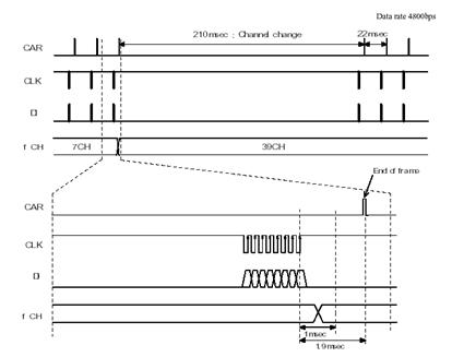
|
|
Transmitter: Frequency CH change flow chart
Figure
D.14: TX, Frequency CH change Flow chart
|
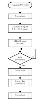
|
|
|
|
� Frequency
CH data is read at the end of data frame. See timing chart for detail.
� After
frequency CH is switched, transmission become possible when CLK is outputted.
Receiver:
Frequency channel change timing
� Following
shows timing chart at time when the receiver frequency channel is changed from
15 to 32 channel.
� Channel
data will be read at the end of frame and the data will be set at next frame.
If channel data is changed at 1 msec or later after final clock (CLK), the data
will be read at next frame.
� The
figure shows the example that data size is one byte. Data will be read by 22
msec span.
� Data
reception is not possible during channel switching period (approx. 210 msec.).
The channel switching time is same at any channel set.
� Reception
will stop and CLK will not be outputted during channel switching.
� Frequency
channel change must be done at the same time for both TX and RX.
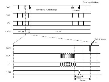
Figure
D.15: RX, Frequency CH change timing
Receiver:
Frequency CH change flow chart
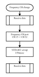
Figure
D.16: RX, Frequency CH change Flow chart
� Frequency
CH data is read at the end of data frame. See timing chart for detail.
� After
frequency CH is switched, reception become possible when CLK is outputted.
Timing at Transmitter -> Receiver switching
� Following
shows timing chart at time when the module switches from transmitter to
receiver.
� T/R
port will be read at the end of frame and the data will be set at next frame.
If T/R port is changed at 1 msec or later after final clock (CLK), the data
will be read at next frame.
� The
figure shows the example with one byte data size and 4800bps data rate.
� Data
reception is not possible during the receiver setting period (approx. 365
msec.).
� Reception
become possible when CLK is outputted.
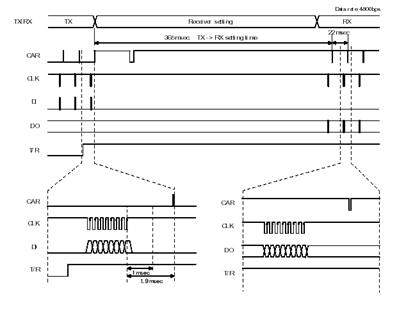
Figure D.17: Timing at TX �> RX
switching
Timing at Receiver -> Transmitter switching
� Following
shows timing chart at time when the module switches from receiver to
transmitter.
� T/R
port will be read at the end of frame and the data will be set at next frame.
If T/R port is changed at 1 msec or later after final clock (CLK), the data
will be read at next frame.
� The
figure shows the example with one byte data size and 4800bps data rate.
� Data
transmission is not possible during the receiver setting period (approx. 200
msec.).
� Transmission
become possible when CLK is outputted.
� As
described in timing at power ON, send dummy data �00H� for 1 � 5 frame at
beginning of transmission to make radio link with receiver.
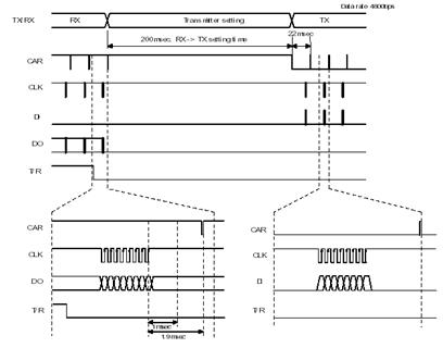
Figure
D.18: Timing at RX -> TX switching
Transmitter <-> Receiver switching flow chart
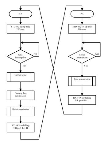
Figure
D.19: TX <-> RX
switching Flow chart
� TX
-> RX or RX -> TX change data will be read at end of frame.
� After
switching TX/RX, transmission and reception is possible when CLK is outputted.
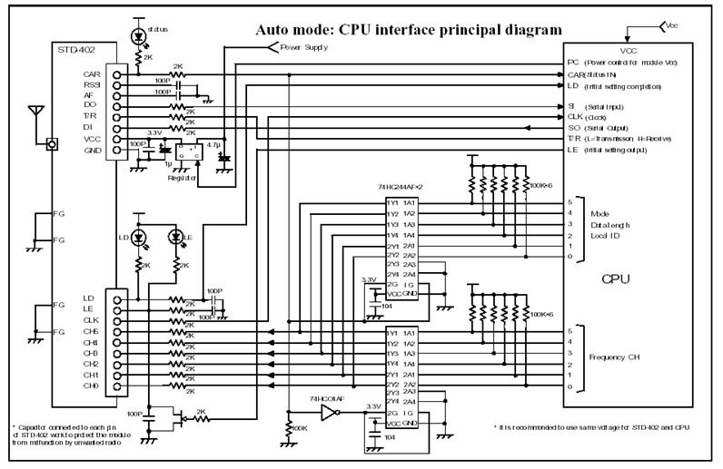
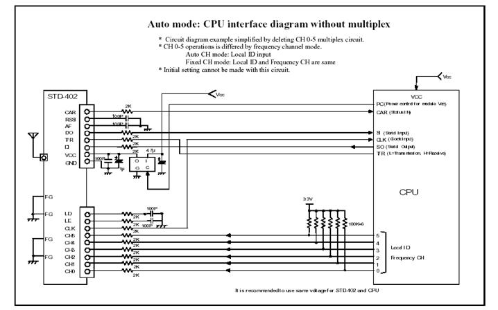
1 ����������������������������� ' Parameters using
to do a Zoom on the PictureMap
2 ����������������������������� Dim r1 As Integer,
X1 As Integer, X2 As Integer, Y1 As Integer, Y2 As Integer
3 ����������������������������� Dim ULeftX As
Integer, ULeftY As Integer, Target As PictureBox
�
4 ����������������������������� Private Sub
C_Close_Click()
5 ����������������������������� 'Close the Serial Port
6 ����������������������������� MSComm1.PortOpen =
False
7������������������������������ 'Close the
Receive_File
8 ����������������������������� Close #1
9 ����������������������������� 'Close the
Send_file
10 ��������������������������� Close #2
11 ��������������������������� 'Close the
Solar_file
12 ��������������������������� Close #3
13 ��������������������������� 'Close the User
Interface Program
14 ��������������������������� 'Close the FormMap
Program
15 ��������������������������� 'Close the
FormDirection Program
16 ��������������������������� Unload FormMap
17 ��������������������������� Unload FormDirection
18 ��������������������������� Unload Me
19 ��������������������������� End
20 ��������������������������� End Sub
21 ��������������������������� Private Sub
C_Connection_Click()
22 ��������������������������� 'Wait for Data
(Sensors Data) to come to the Serial
Port
23 ��������������������������� ' 116 is the length
of the Receive_Message
24 ��������������������������� Do
25�� ��������������������������� DoEvents
26 ��������������������������� Loop Until
MSComm1.InBufferCount >= 116
�
28 ��������������������������� ' Call the function
used to Read Data from Serial
Port ( Read_Data)
29 ��������������������������� ' and in this
function, we will test the Begin and the End Flag
30 ��������������������������� Read_Data
31 ��������������������������� End Sub
32 ��������������������������� Private Sub C_Send_Cancel_Click()
33 ��������������������������� 'Enable the timer
used for Receive Data form serial Port
34 ��������������������������� TimerRun_R.Enabled =
True
35 ��������������������������� 'Disable the SDF (
Sending Data Frame)
36 ��������������������������� SDF.Visible = False
37 ��������������������������� 'clear the TextBoxes
from the data
38���������������������������� T_newPos_inX.Text
= ""
39 ��������������������������� T_newPos_inY.Text
= ""
40 ��������������������������� T_newPos_inZ.Text
= ""
41 ��������������������������� T_newVel_inX.Text
= ""
42 ��������������������������� T_newVel_inY.Text
= ""
43 ��������������������������� T_newVel_inZ.Text
= ""
44 ��������������������������� End Sub
45 ��������������������������� Private Sub
C_Send_Commands_Click()
46 ��������������������������� 'Enable le SDF
(Send_Data_Frame)
47 ��������������������������� SDF.Visible = True
48 ��������������������������� 'Clear the Transmit
Buffer
49 ��������������������������� MSComm1.OutBufferCount
= 0
50 ��������������������������� 'Clear the TextBoxes
from Data
51 ��������������������������� T_newPos_inX.Text
= ""
52 ��������������������������� T_newPos_inY.Text
= ""
53 ��������������������������� T_newPos_inZ.Text
= ""
54 ��������������������������� T_newVel_inX.Text
= ""
55 ��������������������������� T_newVel_inY.Text
= ""
56 ��������������������������� T_newVel_inZ.Text
= ""
57 ��������������������������� 'Set the Cursor in
the first TextBox (new_Position inX)
58 ��������������������������� T_newPos_inX.SetFocus
59 ��������������������������� End������ Sub
60 ��������������������������� Private Sub
C_Send_OK_Click()
61 ��������������������������� 'Testing the status
of the new information (TextBoxes)
62�� If (UserInterface.T_newPos_inX.Text =
"" Or UserInterface.T_newPos_inY.Text = "" Or 63�� UserInterface.T_newPos_inZ.Text =
"" _
64�� Or UserInterface.T_newVel_inX.Text =
"" Or UserInterface.T_newVel_inY.Text = "" Or 65�� UserInterface.T_newVel_inZ = "")
Then
66�� MsgBox (" SORRY, but you should put a
number in these TEXTBOXES !!!!!")
67�� T_newPos_inX.SetFocus
68 ��������������������������� Else
69������� 'Disable the Timer using for Read_Data
70������� TimerRun_R.Enabled = False
���
71��� ������������������������ 'call
the function used for writing Commands in the Transmit Buffer
72�� ������������������������� �Write_Commands
���
73��� ������������������������ 'Disable
the SDF (Send_Data_Frame)
74��� ������������������������ SDF.Visible
= False
���
75��� ������������������������ 'Enable
the Timer used for Reading Data
76��� ������������������������ TimerRun_R.Enabled
= True
77 ��������������������������� End If
78 ��������������������������� End Sub
79 ��������������������������� Private Sub
C_Solar_Radiation_Click()
80 ��������������������������� 'Close the
Solar_file.rad
81 ��������������������������� Close #3
82 ��������������������������� 'Execute the Program
used to draw the Position of the
83 ��������������������������� 'ALTERNATIVE-Lotte
in the 3D (three Dimensions) with
84 ��������������������������� '��� the value of the Solar Radiation
85 ��������������������������� Shell
"C:\3D\Jet.exe", vbNormalFocus
86 ��������������������������� End Sub
87 ��������������������������� Private Sub
Form_Load()
88 ��������������������������� 'Initialisation the
form of the User Interface
89 ��������������������������� UserInterface.Width
= Screen.Width
90 ��������������������������� UserInterface.Height
= Screen.Height
91 ��������������������������� 'Initialisation of
the position of the ALTERNATIVE-Lotte on the MAP
92 ��������������������������� CenterX0 = 3
93 ��������������������������� CenterY0 =
PictureMap.Height - 1702
94 ��������������������������� 'Initialisation of
the Counter used for drawing
95 ��������������������������� '� the Wind Vector and the Solar
96 ��������������������������� CountW = 1
98 ��������������������������� 'Initialisation of
the Value used to display
99 ��������������������������� 'the position and
the direction in the large view
100 ������������������������� CLK_M = False
101 ������������������������� CLK_D = False
102�� 'Open the file (Send_file) that the user
used it to put the Telegram (Message) that he will 103�� send to the ALTERNATIVE-Lotte
104�� Open "C:\User
Interface\Data\Send_file.snd" For Binary Access Write As #2
105�� SI = 0
106��� ' Open the file (Receive_file) that the
user used it to put the Telegram (Message) that he 107��� will recevie from the ALTERNATIVE-Lotte
108��� Open "C:\User
Interface\Data\Receive_file.rcv" For Binary Access Write As #1
109��� RI = 0
110��� 'Open the file (Solar_File) that the user
used it to put the value of the Solar Radiation
111���� Open "C:\User
Interface\Data\Solar_file.rad" For Binary Access Write As #3
112���� SRI = 0
113 ������������������������� 'Set the drive an path
for the JPG or BMP image and the Mouse icon
114���� ChDrive Left$(App.Path, 2)
115���� ChDir App.Path
�� ������
116���� 'The shape control for the ZoomBox or
frame is loaded dynamically
117���� 'at runtime
118���� Controls.Add "vb.shape",
"shpZoomBox", PictureMap
119������� Set Target = FormMap.PictureMap_Z
120������� Target.Width =
FormMap.PictureMap_Z.Width
121������� Target.Height =
FormMap.PictureMap_Z.Height
122� ������������������������ 'Disable
the SDF (Send_Data_Frame)
123�� ����������������������� SDF.Visible
= False
124 ������������������������� 'Disable the Solar
Radiation Command
125 ������������������������� C_Solar_Radiation.Enabled
= False
126 ������������������������� 'Test the Status of
the serial Port
127 ������������������������� If
(Status_Port(MSComm1, 3) = False) Then
128���� MsgBox "SORRY!!!, This port is not
Available (used by another application)"
129���� End
130 ������������������������� Else
131��� ���������������������� '
Initialisation of the serial port
132��� ���������������������� MSComm1.CommPort
= 3
133�� ����������������������� MSComm1.Settings
= "9600,E,8,2"
134��� ���������������������� MSComm1.Handshaking
= comRTSXOnXOff
135��� ���������������������� MSComm1.RTSEnable
= True
136�� ����������������������� MSComm1.InputMode
= comInputModeText
137�� ����������������������� MSComm1.InputLen
= 116
138�� ����������������������� MSComm1.PortOpen
= True
139�� ����������������������� 'Initialisation
of the value of the Recevie_Message
140��� ���������������������� RMessage.DataIn_AX
= "0"
141��� ���������������������� RMessage.DataIn_AY
= "0"
142��� ���������������������� RMessage.DataIn_AZ
= "0"
143��� ���������������������� RMessage.DataIn_AVX
= "0"
144��� ���������������������� RMessage.DataIn_AVY
= "0"
145��� ���������������������� RMessage.DataIn_AVZ
= "0"
146��� ���������������������� RMessage.DataIn_Azt
= "0"
147��� ���������������������� RMessage.DataIn_WX
= "0"
148��� ���������������������� RMessage.DataIn_WY
= "0"
149��� ���������������������� RMessage.DataIn_WZ
= "0"
150��� ���������������������� RMessage.DataIn_SX
= "0"
151��� ���������������������� RMessage.DataIn_SY
= "0"
152��� ���������������������� RMessage.DataIn_SZ
= "0"
153��� ���������������������� RMessage.DataIn_Temp
= "0"
154��� ���������������������� 'Set
the Interval of the timer
155��� ���������������������� TimerRun_R.Interval
= 500
�����
156��� ���������������������� 'Enable
the Timer used for Reading Data
157��� ���������������������� TimerRun_R.Enabled
= True
158 ������������������������� End If
159 ������������������������� End Sub
160 ������������������������� Private Sub
PictureDir_Click()
161 ������������������������� 'Enable the
From_Direction
162 ������������������������� FormDirection.Visible
= True
163 ������������������������� 'Disable the SDF
(Sending_Data_Frame)
164 ������������������������� SDF.Visible = False
165�������������������������� FormDirection.SetFocus
166 ������������������������� 'Close the FormMap
167 ������������������������� Unload FormMap
168 ������������������������� CLK_D = True
169 ������������������������� If (Azimuts < 0)
Then
170���� YD_Z = 1900 - (1650 * Cos((Azimuts * PI) /
180))
171���� XD_Z = 2450 +
(1650 * Sin((Azimuts * PI) / 180))
172���� FormDirection.PictureDir_Z.Line (2450,
1900)-(XD_Z, YD_Z), RGB(255, 0, 0)
173 ������������������������� Else
174���� YD_Z = 1900 - (1650 * Cos((Azimuts * PI) /
180))
175���� XD_Z = 2480 +
(1650 * Sin((Azimuts * PI) / 180))
176���� FormDirection.PictureDir_Z.Line (2480,
1900)-(XD_Z, YD_Z), RGB(255, 0, 0)
177 ������������������������� End If
178 ������������������������� End Sub
Private Sub
PictureMap_MouseDown(Button As Integer, Shift As Integer, X As
����������� Single, Y As Single)
180� ������������������������ 'Get
the Position of the Mouse_Down
181 ������������������������� X1 = X
182 ������������������������� Y1 = Y
183��� ���������������������� 'Get
the position of the MouseDown.It is mean get
184��� ���������������������� 'the
X and Y when the User press the MouseDown
185��� ���������������������� Controls("shpZoomBox").Left
= X1
186��� ���������������������� Controls("shpZoomBox").Top
= Y1
187��� ���������������������� Controls("shpZoomBox").Width
= 0
188��� ���������������������� Controls("shpZoomBox").Height
= 0
189��� ���������������������� Controls("shpZoomBox").BorderStyle
= 3
190��� ���������������������� Controls("shpZoomBox").Visible
= True
191 ������������������������� End Sub
Private Sub
PictureMap_MouseMove(Button As Integer, Shift As Integer, X As
���������� Single, Y As Single)
193 ������������������������� 'Call the function
used to do a Zoom
194 ������������������������� ZoomBoxArea X1, X, Y1,
Y
���
195��� ���������������������� If
Controls("shpZoomBox").Visible = True Then
���
196������ 'Change the Mouse Icon
197������ PictureMap.MousePointer = vbCustom
198������ PictureMap.MouseIcon =
LoadPicture("cursor20.ico")
���
199������ Controls("shpZoomBox").Width =
minX(X1, X)
200������ Controls("shpZoomBox").Height
= minY(Y1, Y)
���
201��� ���������������������� End
If
202 ������������������������� End Sub
Private Sub
PictureMap_MouseUp(Button As Integer, Shift As Integer, X As Single,
����������� Y As Single)
204 ������������������������� 'Enable the FormMap
205 ������������������������� FormMap.Visible = True
206 ������������������������� FormMap.SetFocus
207 ������������������������� 'Close the
FormDirection
208 ������������������������� Unload FormDirection
209 ������������������������� FormMap.C_ZoomMap.Visible
= True
210 ������������������������� CLK_M = True
211��� ���������������������� Controls("shpZoomBox").Visible
= False
212��� ���������������������� PictureMap.MousePointer
= vbArrow
���
213��� ���������������������� 'Get
the position of the Mouse_Up
214��� ���������������������� X2
= X
215��� ���������������������� Y2
= Y
���
216��� ���������������������� ZoomBoxArea
X1, X2, Y1, Y2
���
217��� ���������������������� 'The
StretchBlt API function copies a bitmap from a source
218��� ���������������������� 'rectangle
into a destination rectangle.
219��� ���������������������� r1
= StretchBlt(Target.hdc, 0, 0, Target.Width, Target.Height, PictureMap.hdc,
ULeftX, 220� ULeftY, minX(X1, X2),
minY(Y1, Y2), SRCCOPY)
���
221��� ���������������������� '
show the updated image
222��� ���������������������� Target.Refresh
' show the updated image
���
223��� ���������������������� 'Disable
the SDF (Sending_Data_Frame)
224��� ���������������������� SDF.Visible
= False
225 ������������������������� End Sub
226 ������������������������� Private Sub
T_newvel_inX_KeyPress(KeyAscii As Integer)
227 ������������������������� 'Testing the status of
the TextBoxes, so if it is not clear, jump to the other
228 ������������������������� �If (T_newVel_inX.Text <> ""
And KeyAscii = 13) Then
229����� T_newVel_inY.SetFocus
230����� ElseIf (KeyAscii = 27) Then
231�����
T_newPos_inZ.SetFocus
232�����
T_newVel_inX.Text = ""
233����� ElseIf (T_newVel_inX.Text = "")
Then
234����� T_newVel_inX.SetFocus
235 ������������������������� End If
236 ������������������������� End Sub
237 ������������������������� Private Sub
T_newvel_inY_KeyPress(KeyAscii As Integer)
238 ������������������������� 'Testing the status of
the TextBoxes, so if it is not clear, jump to the other
239 ������������������������� If (T_newVel_inY.Text
<> "" And KeyAscii = 13) Then
240����� T_newVel_inZ.SetFocus
241����� ElseIf (KeyAscii = 27) Then
242����� T_newVel_inX.SetFocus
243����� T_newVel_inY.Text = ""
244����� ElseIf (T_newVel_inY.Text = "")
Then
245����� T_newVel_inY.SetFocus
246 ������������������������� End If
247 ������������������������� End Sub
248 ������������������������� Private Sub
T_newvel_inZ_KeyPress(KeyAscii As Integer)
249 ������������������������� 'Testing the status of
the TextBoxes, so if it is not clear, jump to the other
250 ������������������������� If (T_newVel_inZ.Text
<> "" And KeyAscii = 13) Then
251���� C_Send_OK.SetFocus
252���� ElseIf (KeyAscii = 27) Then
253���� T_newVel_inY.SetFocus
254���� T_newVel_inZ.Text = ""
255���� ElseIf (T_newVel_inZ.Text = "")
Then
256���� T_newVel_inZ.SetFocus
257 ������������������������� End If
258 ������������������������� End Sub
259 ������������������������� Private Sub
T_newPos_inX_KeyPress(KeyAscii As Integer)
260 ������������������������� 'Testing the status of
the TextBoxes, so if it is not clear, jump to the other
261 ������������������������� If (T_newPos_inX.Text
<> "" And KeyAscii = 13) Then
262����� T_newPos_inY.SetFocus
263����� ElseIf (T_newPos_inX = "") Then
264����� T_newPos_inX.SetFocus
265 ������������������������� End If
266 ������������������������� End Sub
267 ������������������������� Private Sub
T_newPos_inY_KeyPress(KeyAscii As Integer)
268 ������������������������� 'Testing the status of
the TextBoxes, so if it is not clear, jump to the other
269 ������������������������� If (T_newPos_inY.Text
<> "" And KeyAscii = 13) Then
270����� T_newPos_inZ.SetFocus
271����� ElseIf (KeyAscii = 27) Then
272�����
T_newPos_inX.SetFocus
273�����
T_newPos_inY.Text = ""
274����� ElseIf (T_newPos_inY.Text = "")
Then
275����� T_newPos_inY.SetFocus
276 ������������������������� End If
277 ������������������������� End Sub
278 ������������������������� Private Sub
T_newPos_inZ_KeyPress(KeyAscii As Integer)
279 ������������������������� 'Testing the status of
the TextBoxes, so if it is not clear, jump to the other
280 ������������������������� If (T_newPos_inZ.Text
<> "" And KeyAscii = 13) Then
281���� T_newVel_inX.SetFocus
282���� ElseIf (KeyAscii = 27) Then
283����
T_newPos_inY.SetFocus
284����
T_newPos_inZ.Text = ""
285���� ElseIf (T_newPos_inZ.Text = "")
Then
286���� T_newPos_inZ.SetFocus
287 ������������������������� End If
288 ������������������������� End Sub
289 ������������������������� Private Sub
TimerRun_R_Timer()
290 ������������������������� 'Wait for Data
(Sensors Data) to come to the Serial
Port
291 ������������������������� '116 is the length of
the Receive_Message
292 ������������������������� Do
293�� ������������������������� DoEvents
294� ������������������������ 'Enable
The Solar Radiation Command
295� ������������������������ 'because
when the program stop here
296� ������������������������ 'It
is mean that the travel of the
297� ������������������������ 'ALTERNATIVE-Lotte
is finished
298� ������������������������ C_Solar_Radiation.Enabled
= True
299 ������������������������� Loop Until
MSComm1.InBufferCount >= 116
�
300� ������������������������ 'Disable
the Solar Radiation Command
301� ������������������������ 'because
when the program continue
302� ������������������������ 'It
is mean that the ALTERNATIVE-Lotte
303� ������������������������ 'continue
its tavel
304� ������������������������ C_Solar_Radiation.Enabled
= False
�
305 ������������������������� 'Call the function
used to Read Data
306 ������������������������� Read_Data
307�������������������������� End Sub
308 ������������������������� 'these 3 functions
minX, minY and ZoomBoxArea are used
309 ������������������������� 'to do a Zoom on the
position of the ALTERNATIVE - Lotte
310 ������������������������� Public Function
minX(X1, X2)
�����
311����� If X1 < X2 Then
312����� minX = X2 - X1
313����� Controls("shpZoomBox").Left =
X1
314����� Else
315����� minX = X1 - X2
316����� Controls("shpZoomBox").Left =
X1 - minX
317����� End If�����
318 ������������������������� End Function
319 ������������������������� Public Function
minY(Y1, Y2)
�����
320����� If Y1 < Y2 Then
321����� minY = Y2 - Y1
322����� Controls("shpZoomBox").Top = Y1
323����� Else
324����� minY = Y1 - Y2
325����� Controls("shpZoomBox").Top = Y1
- minY
326����� End If
327 ������������������������� End Function
328 ������������������������� Public Sub
ZoomBoxArea(X1, X2, Y1, Y2)
329���� If X1 < X2 And Y1 > Y2 Then
330���� ULeftX = X1
331���� ULeftY = Y2
332���� ElseIf X1 > X2 And Y1 > Y2 Then
333���� ULeftX = X2
334���� ULeftY = Y2
335���� ElseIf X1 > X2 And Y1 < Y2 Then
336���� ULeftX = X2
337���� ULeftY = Y1
338���� Else
339���� ULeftX = X1
340���� ULeftY = Y1
341���� End If
342 ������������������������� End Sub
Visual
Basic code for the library (Library_RW) used in the user interface program
343 ������������������������� Public Const PI =
3.141592
344 ������������������������� 'Declare Sub Sleep Lib
"kernel32" (ByVal dwMilliseconds As Long)
345 ������������������������� 'these two functions
are used to do a Zoom for a picture
346 ������������������������� Public Declare
Function BitBlt Lib "gdi32" (ByVal hDestDC As Long, ByVal X As
347 ������������������������� Long, ByVal Y As Long,
ByVal nWidth As Long, ByVal nHeight As Long, ByVal
hSrcDC As
Long, ByVal xSrc As Long, ByVal ySrc As Long, ByVal dwRop As�
349 ������������������������� Long) As Long
350� Public Declare Function StretchBlt Lib
"gdi32" (ByVal hdc As Long, ByVal X As Long, 351� ByVal Y As Long, ByVal nWidth As Long, ByVal
nHeight As Long, ByVal hSrcDC As 352�
Long, ByVal xSrc As Long, ByVal ySrc As Long, ByVal nSrcWidth As Long,
ByVal 353� nSrcHeight As Long, ByVal
dwRop As Long) As Long
354� Public Const SRCAND = &H8800C6��������� ' (DWORD) dest = source AND dest
355� Public Const SRCCOPY = &HCC0020�������� ' (DWORD) dest = source
355� Public Const SRCERASE = &H440328������� ' (DWORD) dest = source AND (NOT dest)
356� Public Const SRCINVERT = &H660046������ ' (DWORD) dest = source XOR dest
357� Public Const SRCPAINT = &HEE0086������� ' (DWORD) dest = source OR dest
358 ������������������������� 'Structure of the
Receive_Message
359 ������������������������� Public Type
Struct_RMessage
360����� Begin_RFlag As String���������� ' The really type is Byte
361����� Length_RMessage As String������ ' The really type is Interger
362����� DataIn_AX As String������������ ' The really type is Single
363����� DataIn_AY As String������������ ' The really type is Single
364����� DataIn_AZ As String������������ ' The really type is Single
365����� DataIn_AVX As String����������� ' The really type is Single
366����� DataIn_AVY As String����������� ' The really type is Single
367����� DataIn_AVZ As String����������� ' The really type is Single
368����� DataIn_Azt As String����������� ' The really type is Single
369 �����DataIn_WX As String������������ ' The really type is Single
370����� DataIn_WY As String������������ ' The really type is Single
371����� DataIn_WZ As String������������ ' The really type is Single
372����� DataIn_SX As String������������ ' The really type is Single
373����� DataIn_SY As String������������ ' The really type is Single
374����� DataIn_SZ As String������������ ' The really type is Single
375����� DataIn_Temp As String������������ ' The really type is Single
376����� End_RFlag As String�� ����������' The really type is Byte
377 ������������������������� End Type
378 ������������������������� Public RMessage As
Struct_RMessage
379 ������������������������� 'String (Variable)
used for Read Data from Serial
Port
380 ������������������������� Public Receive_Message
As String
381 ������������������������� 'Structure of the
Send_Message
382 ������������������������� Public Type
Struct_SMessage
383����� Begin_SFlag As String���������� ' The really type is Byte
384����� Length_SMessage As String������ ' The really type is Interger
385����� DataOut_PX As String����������� ' The really type is Single
386����� DataOut_PY As String����������� ' The really type is Single
387����� DataOut_PZ As String����������� ' The really type is Single
388����� DataOut_VelX As String��������� ' The really type is Single
389����� DataOut_VelY As String��������� ' The really type is Single
390����� DataOut_VelZ As String��������� ' The really type is Single
391����� End_SFlag As String������������ ' The really type is Byte
392 ������������������������� End Type
393 ������������������������� Public SMessage As
Struct_SMessage
394 ������������������������� 'String (Variable)
used for Send Data to Serial
Port
395 ������������������������� Public Send_Message As
String
396 ������������������������� 'Parameters used to
save the Old Data
397�������������������������� Public Acc_inX As
Single
398�������������������������� Public Acc_inY As
Single
399 ������������������������� Public Acc_inZ As
Single
400 ������������������������� Public Ang_vel_inX As
Single
401 ������������������������� Public Ang_vel_inY As
Single
402 ������������������������� Public Ang_vel_inZ As
Single
403 ������������������������� Public Azimuts As
Single
404 ������������������������� Public Wind_inX As
Single
405 ������������������������� Public Wind_inY As
Single
406 ������������������������� Public Wind_inZ As
Single
407 ������������������������� Public Solar_inX As
Single
408 ������������������������� Public Solar_inY As
Single
409 ������������������������� Public Solar_inZ As
Single
410 ������������������������� Public Temp As Single
411 ������������������������� 'Parameters used to get
the Velocity and the Position
412�������������������������� Public Vel_inX As
Single
413 ������������������������� Public Vel_inY As
Single
414 ������������������������� Public Vel_inZ As
Single
415 ������������������������� Public Pos_inX As
Single
416 ������������������������� Public Pos_inY As
Single
417 ������������������������� Public Pos_inZ As
Single
418 ������������������������� ' Parameters used for
drawing the Position
419 ������������������������� '���� of the ALTERNATIVE-Lotte on the MAP
420 ������������������������� Public CenterX As
Single
421 ������������������������� Public CenterY As
Single
422 ������������������������� Public CenterX0 As
Single
423 ������������������������� Public CenterY0 As
Single
424 ������������������������� Public CLK_M As
Boolean
425 ������������������������� ' Parameters used for
drawing the Direction
426 ������������������������� '���� of the ALTERNATIVE-Lotte
427 ������������������������� Public XD As Single
428 ������������������������� Public YD As Single
429 ������������������������� Public XD_Z As Single
430 ������������������������� Public YD_Z As Single
431 ������������������������� Public CLK_D As
Boolean
432 ������������������������� 'Parameters used to
put the Wind Vector
432 ������������������������� Public RW As
Single������� 'Wind Power
433 ������������������������� Public CountW As
Integer
434 ������������������������� 'Parameters used to
put the Solar Radiation
435 ������������������������� Public RS As
Single������� 'Solar Radiation
436 ������������������������� 'Paramters used to put
the Telegram in the file
437 ������������������������� Public RI As Integer���
438 ������������������������� Public SI As Integer
439 ������������������������� Public SRI As Integer
440 ������������������������� Public Function
Read_Data() As Boolean
441 ������������������������� ' Read the Contain of
the Receive Buffer
442 ������������������������� Receive_Message =
UserInterface.MSComm1.Input
443 ������������������������� If (Read_Data) Then
444����� 'Save the old position
445����� Acc_inX = Val(RMessage.DataIn_AX)
446� ����Acc_inY = Val(RMessage.DataIn_AY)
447����� Acc_inZ = Val(RMessage.DataIn_AZ)
448����� Ang_vel_inX = Val(RMessage.DataIn_AVX)
449����� Ang_vel_inY = Val(RMessage.DataIn_AVY)
450����� Ang_vel_inZ = Val(RMessage.DataIn_AVZ)
451����� Azimuts = Val(RMessage.DataIn_Azt)
452����� Wind_inX = Val(RMessage.DataIn_WX)
453����� Wind_inY = Val(RMessage.DataIn_WY)
454����� Wind_inZ = Val(RMessage.DataIn_WZ)
455����� Solar_inX = Val(RMessage.DataIn_SX)
456����� Solar_inY = Val(RMessage.DataIn_SY)
457����� Solar_inZ = Val(RMessage.DataIn_SZ)
458����� Temp = Val(RMessage.DataIn_Temp)
459 ������������������������� End If
460 ������������������������� ' Call the function
used to convert from Hex Format to Decimal Format
461 ������������������������� UserInterface.SC1.Reset
462 ������������������������� UserInterface.SC1.AddCode
UserInterface.txtCodeHex2Dec.Text
463 ������������������������� RMessage.Begin_RFlag =
Val("&H" & Left(Receive_Message, 1))
464 ������������������������� RMessage.Length_RMessage
= Val("&H" & Mid(Receive_Message, 2, 2))
465 ������������������������� RMessage.DataIn_AX =
UserInterface.SC1.Run("compute", Mid(Receive_Message, 4, 8))
466 ������������������������� RMessage.DataIn_AY =
UserInterface.SC1.Run("compute", Mid(Receive_Message, 12, 8))
467 ������������������������� RMessage.DataIn_AZ =
UserInterface.SC1.Run("compute", Mid(Receive_Message, 20, 8))
468 ������������������������� RMessage.DataIn_AVX =
UserInterface.SC1.Run("compute", Mid(Receive_Message, 28, 8))
469�������������������������� RMessage.DataIn_AVY
= UserInterface.SC1.Run("compute", Mid(Receive_Message, 36, 8))
470 ������������������������� RMessage.DataIn_AVZ =
UserInterface.SC1.Run("compute", Mid(Receive_Message, 44, 8))
471 ������������������������� RMessage.DataIn_Azt =
UserInterface.SC1.Run("compute", Mid(Receive_Message, 52, 8))
472 ������������������������� RMessage.DataIn_WX =
UserInterface.SC1.Run("compute", Mid(Receive_Message, 60, 8))
473 ������������������������� RMessage.DataIn_WY =
UserInterface.SC1.Run("compute", Mid(Receive_Message, 68, 8))
474 ������������������������� RMessage.DataIn_WZ =
UserInterface.SC1.Run("compute", Mid(Receive_Message, 76, 8))
475 ������������������������� RMessage.DataIn_SX =
UserInterface.SC1.Run("compute", Mid(Receive_Message, 84, 8))
476 ������������������������� RMessage.DataIn_SY =
UserInterface.SC1.Run("compute", Mid(Receive_Message, 92, 8))
477 ������������������������� RMessage.DataIn_SZ =
UserInterface.SC1.Run("compute", Mid(Receive_Message, 100, 8))
478 ������������������������� RMessage.DataIn_Temp =
UserInterface.SC1.Run("compute", Mid(Receive_Message, 108, 8))
479 ������������������������� RMessage.End_RFlag =
Val("&H" & Right(Receive_Message, 1))
480 ������������������������� ' Testing the
Begin_Flag and the End_Flag for each Receive_Message
481 ������������������������� If
(RMessage.Begin_RFlag <> 2 Or RMessage.End_RFlag <> 3) Then
482�� ����������������������� '
In this section the Begin_Flag or the End_Flag is NOT Correct
483� ������������������������ Read_Data
= False
��
484�� ����������������������� '
Display the Old Data
485��� ���������������������� UserInterface.L_Acc_inX.Caption
= Acc_inX
486��� ���������������������� UserInterface.L_Acc_inY.Caption
= Acc_inY
487��� ���������������������� UserInterface.L_Acc_inZ.Caption
= Acc_inZ
489��� ���������������������� UserInterface.L_Ang_inX.Caption
= Ang_vel_inX
490��� ���������������������� UserInterface.L_Ang_inY.Caption
= Ang_vel_inY
491��� ���������������������� UserInterface.L_Ang_inZ.Caption
= Ang_vel_inZ
492�� ����������������������� UserInterface.L_Wind_inX.Caption
= Wind_inX
493��� ���������������������� UserInterface.L_Wind_inY.Caption
= Wind_inY
494��� ���������������������� UserInterface.L_Wind_inZ.Caption
= Wind_inZ
495��� ���������������������� UserInterface.L_Solar_inX.Caption
= Solar_inX
496��� ���������������������� UserInterface.L_Solar_inY.Caption
= Solar_inY
497��� ���������������������� UserInterface.L_Solar_inZ.Caption
= Solar_inZ
498��� ���������������������� UserInterface.L_Temp.Caption
= Temp
499��� ���������������������� UserInterface.L_Vel_inX.Caption
= Vel_inX
500��� ���������������������� UserInterface.L_Vel_inY.Caption
= Vel_inY
501��� ���������������������� UserInterface.L_Vel_inZ.Caption
= Vel_inZ
501��� ���������������������� UserInterface.L_Pos_inX.Caption
= Pos_inX
502��� ���������������������� UserInterface.L_Pos_inY.Caption
= Pos_inY
503��� ���������������������� UserInterface.L_Pos_inZ.Caption
= Pos_inZ
�������
503��� ���������������������� 'display
the status of the connection to the user
504��� ���������������������� UserInterface.L_Connection.Caption
= " TAKE CARE !!!! , there is NO connection 505� �������������������������������� between
the Base Station and the ALTERNATIVE-Lotte"
506��� ���������������������� UserInterface.Pic_statusOK.Visible
= True
507��� ���������������������� UserInterface.Pic_statusNO.Visible
= False
508 ������������������������� Else
509�� ����������������������� '
In this Section the Begin_Flag and the End_Flag are Correct
510� ������������������������ Read_Data = True
��
511�� ����������������������� UserInterface.Text1.Text
= Val(UserInterface.Text1.Text) + 1
512�� ����������������������� '
Display the sensors data in the RDF (Receive_Data_Frame)
513��� ���������������������� UserInterface.L_Acc_inX.Caption
= Left(RMessage.DataIn_AX, 8)
514��� ���������������������� UserInterface.L_Acc_inY.Caption
= Left(RMessage.DataIn_AY, 8)
515��� ���������������������� UserInterface.L_Acc_inZ.Caption
= Left(RMessage.DataIn_AZ, 8)
516��� ���������������������� UserInterface.L_Ang_inX.Caption
= Left(RMessage.DataIn_AVX, 8)
517��� ���������������������� UserInterface.L_Ang_inY.Caption
= Left(RMessage.DataIn_AVY, 8)
518��� ���������������������� UserInterface.L_Ang_inZ.Caption
= Left(RMessage.DataIn_AVZ, 8)
519��� ���������������������� UserInterface.L_Wind_inX.Caption
= Left(RMessage.DataIn_WX, 8)
520��� ���������������������� UserInterface.L_Wind_inY.Caption
= Left(RMessage.DataIn_WY, 8)
521��� ���������������������� UserInterface.L_Wind_inZ.Caption
= Left(RMessage.DataIn_WZ, 8)
522��� ���������������������� UserInterface.L_Solar_inX.Caption
= Left(RMessage.DataIn_SX, 8)
523��� ���������������������� UserInterface.L_Solar_inY.Caption
= Left(RMessage.DataIn_SY, 8)
524��� ���������������������� UserInterface.L_Solar_inZ.Caption
= Left(RMessage.DataIn_SZ, 8)
525��� ���������������������� UserInterface.L_Temp.Caption
= Left(RMessage.DataIn_Temp, 8)
�������
526��� ���������������������� 'Save
the Data
527��� ���������������������� Acc_inX
= Left(RMessage.DataIn_AX, 8)
528��� ���������������������� Acc_inY
= Left(RMessage.DataIn_AY, 8)
529��� ���������������������� Acc_inZ
= Left(RMessage.DataIn_AZ, 8)
530��� ���������������������� Ang_vel_inX
= Left(RMessage.DataIn_AVX, 8)
531��� ���������������������� Ang_vel_inY
= Left(RMessage.DataIn_AVY, 8)
532��� ���������������������� Ang_vel_inZ
= Left(RMessage.DataIn_AVZ, 8)
533��� ���������������������� Azimuts
= Left(RMessage.DataIn_Azt, 8)
534�� ����������������������� Wind_inX
= Left(RMessage.DataIn_WX, 8)
535��� ���������������������� Wind_inY
= Left(RMessage.DataIn_WY, 8)
536�� ����������������������� Wind_inZ
= Left(RMessage.DataIn_WZ, 8)
537��� ���������������������� Solar_inX
= Left(RMessage.DataIn_SX, 8)
538��� ���������������������� Solar_inY
= Left(RMessage.DataIn_SY, 8)
539��� ���������������������� Solar_inZ
= Left(RMessage.DataIn_SZ, 8)
540��� ���������������������� Temp
= Left(RMessage.DataIn_Temp, 8)
����
541�� ����������������������� 'Put
the Sensors_Data in the Recevie_File
542�� ����������������������� 'Put
#1, (1 + 60 * RI), Begin_RFlag
543�� ����������������������� 'Put
#1, (2 + 60 * RI), Length_RMessage
544�� ����������������������� Put
#1, (4 + 60 * RI), Acc_inX
545�� ����������������������� Put
#1, (8 + 60 * RI), Acc_inY
546�� ����������������������� Put
#1, (12 + 60 * RI), Acc_inZ
547�� ����������������������� Put
#1, (16 + 60 * RI), Ang_vel_inX
548�� ����������������������� Put
#1, (20 + 60 * RI), Ang_vel_inY
549�� ����������������������� Put
#1, (24 + 60 * RI), Ang_vel_inZ
550�� ����������������������� Put
#1, (28 + 60 * RI), Azimuts
551�� ����������������������� Put
#1, (32 + 60 * RI), Wind_inX
552�� ����������������������� Put
#1, (36 + 60 * RI), Wind_inY
553�� ����������������������� Put
#1, (40 + 60 * RI), Wind_inZ
554�� ����������������������� Put
#1, (44 + 60 * RI), Solar_inX
555�� ����������������������� Put
#1, (48 + 60 * RI), Solar_inY
556�� ����������������������� Put
#1, (52 + 60 * RI), Solar_inZ
557�� ����������������������� Put
#1, (56 + 60 * RI), Temp
558�� ����������������������� 'Put
#1, (60 + 60 * RI), End_RFlag
559�� ����������������������� RI
= RI + 1
��
560��� ���������������������� 'Call
the function used to Calculate the Velocity of the ALTERNATIVE-Lotte
��������� ���������������������� Calculate_Velocity
���
561��� ���������������������� 'Call
the function used to Calculate the Position of the ALTERNATIVE-Lotte
���������� ��������������������� Calculate_Position
���
562��� ���������������������� 'Get
the position of the Center of the Circle
563��� ���������������������� 'used
to put the position of the ALTERNATIVE-Lotte
564��� ���������������������� CenterX
= CenterX0 + CSng(UserInterface.L_Pos_inX.Caption)
565��� ���������������������� CenterY
= CenterY0 - CSng(UserInterface.L_Pos_inY.Caption)
������ ������������������������� �
566��� ���������������������� 'Put
the Position on the MAP
567��� ���������������������� �UserInterface.PictureMap.PSet (CenterX,
CenterY), RGB(255, 0, 0)
������������
568��� ���������������������� 'Clear
he old direction of the ALTERNATIVE-Lotte
569��� ���������������������� UserInterface.PictureDir.Cls
570��� ���������������������� FormDirection.PictureDir_Z.Cls
���
571��� ���������������������� 'Put
the Direction in the PictureDir
572��� ���������������������� If
(Azimuts < 0) Then
573���� YD = 850 - (700 * Cos((Azimuts * PI) /
180))
574���� XD = 920 + (700 * Sin((Azimuts * PI) /
180))
575���� UserInterface.PictureDir.Line (920,
850)-(XD, YD), RGB(255, 0, 0)
576��� ���������������������� Else
577����� YD = 850 - (700 * Cos((Azimuts * PI) /
180))
578����� XD = 960 + (700 * Sin((Azimuts * PI) /
180))
579����� UserInterface.PictureDir.Line (960,
850)-(XD, YD), RGB(255, 0, 0)
580��� ���������������������� End
If
���������������
581��� ���������������������� 'Testing
if the user click in the pictureDirection�
(ZOOM)
582��� ���������������������� If
(CLK_D) Then
583����� 'Put the Direction on the
PictureDirection in large View (ZOOM)
584����� If (Azimuts < 0) Then
585����� YD_Z = 1900 - (1650 * Cos((Azimuts * PI)
/ 180))
586����� XD_Z = 2450 +
(1650 * Sin((Azimuts * PI) / 180))
587����� FormDirection.PictureDir_Z.Line (2450,
1900)-(XD_Z, YD_Z), RGB(255, 0, 0)
588����� Else
589����� YD_Z = 1900 - (1650 * Cos((Azimuts * PI)
/ 180))
590����� XD_Z = 2480 +
(1650 * Sin((Azimuts * PI) / 180))
591����� FormDirection.PictureDir_Z.Line (2480,
1900)-(XD_Z, YD_Z), RGB(255, 0, 0)
592����� End If
593��� ���������������������� �End If
�������
594��� ���������������������� 'Put
the Wind Vector (Wind Power) in the PictureWind
�� RW = (Val(UserInterface.L_Wind_inX.Caption)
^ 2 +�
������������
Val(UserInterface.L_Wind_inY.Caption) ^ 2 +
������������
Val(UserInterface.L_Wind_inZ.Caption) ^ 2) ^ (1 / 2)
�� UserInterface.PictureWind.PSet (CountW,
UserInterface.PictureWind.Height - 1365��
������������� � (RW / 13)), RGB(255, 0, 0)
�������
597������� 'Put the Solar Vector (Solar Radiation)
in the PictureSolar
���� RS =
(Val(UserInterface.L_Solar_inX.Caption) ^ 2 +
��������������
Val(UserInterface.L_Solar_inY.Caption) ^ 2 +
��������������
Val(UserInterface.L_Solar_inZ.Caption) ^ 2) ^ (1 / 2)
���� UserInterface.PictureSolar.PSet (CountW,
UserInterface.PictureSolar.Height - 1365���
��������������� �� (RS / 13)), RGB(255, 0, 0)
599��������� CountW = CountW + 2
���
600��� ���������������������� 'Put
the Solar Radiation Data in the Solar_file
601��� ���������������������� Put
#3, (1 + 17 * SRI), Pos_inX
602��� ���������������������� Put
#3, (5 + 17 * SRI), Pos_inY
603��� ���������������������� Put #3, (9 + 17 * SRI),
Pos_inZ
604��� ���������������������� Put #3, (13 + 17 * SRI),
RS
605��� ���������������������� SRI = SRI + 1
���
606��� 'Display the Status of the Connection to
the User
607��� UserInterface.L_Connection.Caption =
"There is a connection between the Base Station 608��� and the ALTERNATIVE-Lotte"
609��� UserInterface.Pic_statusNO.Visible = True
610��� UserInterface.Pic_statusOK.Visible = False
611��� End If
612� ������������������������ 'After
reading the receive message, we clean the receive buffer
613�� ����������������������� UserInterface.MSComm1.InBufferCount
= 0
614� ������������������������ End
Function
615 ������������������������� Public Function
Write_Commands() As Boolean
616� ������������������������ '
Call the function used to convert from Decimal format to Hex format
617 ������������������������� UserInterface.SC1.Reset
618 ������������������������� UserInterface.SC1.AddCode
UserInterface.txtCodeDec2Hex.Text
619 ������������������������� 'configure the Send
Message
620 ������������������������� SMessage.Begin_SFlag =
Hex$(2)
621 ������������������������� SMessage.Length_SMessage
= Hex$(28)
622 ������������������������� If
(Val(UserInterface.T_newPos_inX.Text) =�
������� ������������������������ CInt(Val(UserInterface.T_newPos_inX.Text)))
Then
623����� UserInterface.T_newPos_inX.Text =
(UserInterface.T_newPos_inX.Text &���
".000001")
SMessage.DataOut_PX
= UserInterface.SC1.Run("compute", UserInterface.T_newPos_inX.Text)
625��� Else
626��� SMessage.DataOut_PX =
UserInterface.SC1.Run("compute",��
��������� UserInterface.T_newPos_inX.Text)
627��� End If
�
628 ������������������������� If
(Val(UserInterface.T_newPos_inY.Text) =
����� �������������������������� CInt(Val(UserInterface.T_newPos_inY.Text)))
Then
628����� UserInterface.T_newPos_inY.Text =
UserInterface.T_newPos_inY.Text & ".000001"
� SMessage.DataOut_PY = UserInterface.SC1.Run("compute",
����������� (UserInterface.T_newPos_inY.Text))
630 ������������������������� Else
631���� SMessage.DataOut_PY =
UserInterface.SC1.Run("compute",
���������� (UserInterface.T_newPos_inY.Text))
632�� ����������������������� End
If
633 ������������������������� If
(Val(UserInterface.T_newPos_inZ.Text) =
������ ������������������������� CInt(Val(UserInterface.T_newPos_inZ.Text)))
Then
634����� UserInterface.T_newPos_inZ.Text =
UserInterface.T_newPos_inZ & ".000001"
� SMessage.DataOut_PZ =
UserInterface.SC1.Run("compute",
����������� (UserInterface.T_newPos_inZ.Text))
637 ������������������������� Else
�SMessage.DataOut_PZ =
UserInterface.SC1.Run("compute",
���������� (UserInterface.T_newPos_inZ.Text))
639 ������������������������� End If
640� ������������������������ If
(Val(UserInterface.T_newVel_inX.Text) =
����������
CInt(Val(UserInterface.T_newVel_inX.Text))) Then
641���� UserInterface.T_newVel_inX.Text =
UserInterface.T_newVel_inX.Text & ".000001"
�SMessage.DataOut_VelX =
UserInterface.SC1.Run("compute",
���������� (UserInterface.T_newVel_inX.Text))
643 ������������������������� Else
644���� SMessage.DataOut_VelX =
UserInterface.SC1.Run("compute",�
���������� (UserInterface.T_newVel_inX.Text))
645� ������������������������ End
If
645 ������������������������� If
(Val(UserInterface.T_newVel_inY.Text) =
������ ������������������������� CInt(Val(UserInterface.T_newVel_inY.Text)))
Then
646��� ���������������������� UserInterface.T_newVel_inY.Text
= UserInterface.T_newVel_inY.Text & ".000001"
� SMessage.DataOut_VelY = UserInterface.SC1.Run("compute",�
����������� (UserInterface.T_newVel_inY.Text))
648� ������������������������ �Else
649����� SMessage.DataOut_VelY =
UserInterface.SC1.Run("compute",
����������� (UserInterface.T_newVel_inY.Text))
650� ������������������������ End
If
��� If (Val(UserInterface.T_newVel_inZ.Text) =
�����������
CInt(Val(UserInterface.T_newVel_inZ.Text))) Then
652����� UserInterface.T_newVel_inZ.Text =
UserInterface.T_newVel_inZ.Text & ".000001"
653����� SMessage.DataOut_VelZ =
UserInterface.SC1.Run("compute",
����������� (UserInterface.T_newVel_inZ.Text))
654� ������������������������ Else
� SMessage.DataOut_VelZ =
UserInterface.SC1.Run("compute",
����������� (UserInterface.T_newVel_inZ.Text))
656 ������������������������� �End If
657� ������������������������ SMessage.End_SFlag
= Hex$(3)
658� ������������������������ ����'Put the Data (Commands) in the
Send_Message
659�������� Send_Message = SMessage.Begin_SFlag
& SMessage.Length_SMessage & _
�������������� SMessage.DataOut_PX &
SMessage.DataOut_PY & _
�������������� SMessage.DataOut_PZ &
SMessage.DataOut_VelX & _
�������������� SMessage.DataOut_VelY &
SMessage.DataOut_VelZ & _
������� �������SMessage.End_SFlag
��������������
660� ������������������������ 'Put
the Telegram (Send_Message) in the Send_File
661� ������������������������ Put
#2, (1 + 60 * SI), Send_Message
662� ������������������������ SI
= SI + 1
663� ������������������������ 'send
the Message to the Transmit Buffer
664 ������������������������� UserInterface.MSComm1.Output
= Send_Message
665� ������������������������ 'Set
the Status of the Write_Commands function
665� ������������������������ Write_Commands
= True
666 ������������������������� End Function
667 ������������������������� ' the Goal of this
function is to calculate the Velocity
668� ������������������������ '
of the ALTERNATIVE - Lotte in X, Y and Z
��� � The Velocity is the Integration of the Acceleration
670� ������������������������ Public
Function Calculate_Velocity() As Boolean
671����� Vel_inX = (RMessage.DataIn_AX) *
(UserInterface.TimerRun_R.Interval / 1000)
672� ������������������������ �Vel_inY = (RMessage.DataIn_AY) *
(UserInterface.TimerRun_R.Interval / 1000)
673� ������������������������ �Vel_inZ = (RMessage.DataIn_AZ) *
(UserInterface.TimerRun_R.Interval / 1000)
674� ������������������������ �UserInterface.L_Vel_inX.Caption = Vel_inX
675� ������������������������ �UserInterface.L_Vel_inY.Caption = Vel_inY
676� ������������������������ �UserInterface.L_Vel_inZ.Caption = Vel_inZ
677� ������������������������ �Calculate_Velocity = True
678� ������������������������ �End Function
679� ������������������������ '
the Goal of this function is to calculate the Positon
680� ������������������������ '
of the ALTERNATIVE - Lotte in X, Y and Z
681� ������������������������ '
The Position is the Integration of the Velocity
682� ������������������������ Public
Function Calculate_Position() As Boolean
683� ������������������������ Pos_inX
= Vel_inX * (UserInterface.TimerRun_R.Interval / 1000)
684� ������������������������ Pos_inY
= Vel_inY * (UserInterface.TimerRun_R.Interval / 1000)
685� ������������������������ Pos_inZ
= Vel_inZ * (UserInterface.TimerRun_R.Interval / 1000)
686� ������������������������ UserInterface.L_Pos_inX.Caption
= Pos_inX
687� ������������������������ UserInterface.L_Pos_inY.Caption
= Pos_inY
688� ������������������������ UserInterface.L_Pos_inZ.Caption
= Pos_inZ
689� ������������������������ Calculate_Position
= True
690� ������������������������ End
Function
691� ������������������������ Public
Function Status_Port(cComm As MSComm, lPort As Long) As Boolean
692� ������������������������ 'This
function Test the Status of the Serial
Port
693� ������������������������ 'NOTE
: Do not try to send/receive data while executing this function...!
694� ������������������������ Dim
oldState As Boolean
695� ������������������������ Dim
oldPort As Long
696� ������������������������ '� Get current MSComm Info
697�� ����������������������� oldState
= cComm.PortOpen
698�� ����������������������� oldPort
= cComm.CommPort
699�� ����������������������� '� Change Info
700�� ����������������������� On
Error Resume Next
701��� ���������������������� cComm.PortOpen
= False
702��� ���������������������� cComm.CommPort
= lPort
703�� ����������������������� '� See if Port is Available
704�� ����������������������� Err.Clear
705�� ����������������������� cComm.PortOpen
= True
706�� ����������������������� If
Err Then
707��� ���������������������� Status_Port
= False
708��� ���������������������� Debug.Print
Err.Description
709� ������������������������ Else
710��� ���������������������� Status_Port
= True
711� ������������������������ End
If
712���� cComm.PortOpen = False
713�� ����������������������� '� Set Info Back To Old Data
714��� ���������������������� cComm.CommPort
= oldPort
715��� ���������������������� cComm.PortOpen
= oldState
716��� ���������������������� On
Error GoTo 0
717�� ����������������������� End
Function
/****************************************************************************************************
**
** Project ���������������� :
Diploma Thesis
**
** ������������������������������ The goal of this
program is to initialise the serial port
** ������������������������������ and read from one
serial port and write to another.......
**
*****************************************************************************************************/
/*--
Include files ----------------------------------------------------------*/
1��� #include <stdio.h>���������������������� /* Standard input/output
definitions */
2��� #include <string.h>�������������������� /* String function
definitions */
3��� #include <unistd.h>������������������� /* UNIX standard function
definitions */
4��� #include <fcntl.h>���������������������� /* File Control
definition */
5��� #include <errno.h>��������������������� /* Error number
definitions */
6��� #include "vxWorks.h"
7��� #include "ioLib.h"
8��� #include <sioLib.h>
/******************************************************************************
**
**
COMM_init
**
**
initialize COM-device
**
**----
Parameters -------------------------------------------------------------
**
**
**----
Returnvalue ------------------------------------------------------------
**
** int : 0
if success
** int : -1
if error
**
******************************************************************************/
9�� int COMM_init(char *c_device, int *fd)
10���������������������������� {
11���������������������������� int�������������������� id_com_dev;� /* filename descriptor for the COM */
12���������������������������� int�������������������� speed = 9600;� /* speed for COM */
13���������������������������� int ������������������� SerialControl;
14���������������������������� int�������������������� Parity;
15���������������������������� int�������������������� CharacterSize;
16���������������������������� int�������������������� ioctlvalue;�����������������
������� /*--------------------------------------------------------------------
�������������������������������� ** Open the
COM-Device
�������������������������������� */
17���������������������������� id_com_dev = open
(c_device, O_RDWR ,0);�
18���������������������������� if ( id_com_dev ==
ERROR )�
19���������������������������� {� ���������� ����������� �����������
20������������������������������ ����� perror ("Open_Port : Unable to open
/dev/ ---");��������
21���������������������������� return(-1); ������� ��
������������� /*
�������������������������������� ������ * Could not open the port ��������� �����
�������������� */
22���������������������������� }
�� �����������������������������
23���������������������������� *fd = id_com_dev;
�������������������������������� /*------------------------------------------------------------
������� **��
setting the BAUD-rate to 9600 ............
�������������������������������� */
24���������������������������� if (-1 == ioctl
(id_com_dev,FIOBAUDRATE , speed))
25���������������������������� {
26���������������������������� return(-1);
27���������������������������� }
�������������������������������� /*------------------------------------------------------------
������� **��
Setting the Parity, the Stop bit ................
�������������������������������� */�
28���������������������������� SerialControl =
(CLOCAL | CREAD);
29���������������������������� Parity = PARENB ;
30���������������������������� CharacterSize =
CS8;
if (-1 ==
ioctl (id_com_dev,SIO_HW_OPTS_SET,SerialControl | Parity |�
���������� CharacterSize))
32���������������������������� {
33���������������������������� return(-1);
34���������������������������� }
�������������������������������� /*------------------------------------------------------------
������� **��
Setting the new options of the serial port
�������������������������������� **�� with setting the handshaking protocol
�������������������������������� */����������������������
��������������������������������
35���������������������������� ioctlvalue = ioctl
(id_com_dev, FIOFLUSH, 0);
ioctlvalue
= ioctl (id_com_dev,FIOSETOPTIONS,OPT_TANDEM &~�
����������� OPT_MON_TRAP);�
�38��������������������������� }��
/******************************************************************************
**
** Main
**
** main
program of RWCOM
**----
Returnvalue ------------------------------------------------------------
** 0
******************************************************************************/����������
39���������������������������� �� int maincomRW(int argc, char *argv[])
40���������������������������� {
41������������������������������ char �� �pathserial0[] = "/tyCo/0";��� /* Path of the port 2....*/
42������������������������������ char��� pathserial1[] = "/tyCo/1";��� /* Path of the port 3....*/
43������������������������������ int ����� �ui_byte;������������������������ /* Number of bytes
readed */
44������������������������������ int������ uo_byte;���������������� ��������/* Number of bytes writed */
45������������������������������ char��� *ur_buff;�
/* Buffer used to get the bytes from the serial port */�
46���������������������������� char���
*uw_buff;� /* Buffer used to set the
bytes to the serial port */
47���������������������������� �� ���������� int������ fd1;������ /* file descriptor for the first port */
48������������������������������ int������ fd2;������ /* file descriptor for the second port
*/
49���������������������������� int�����
len_mess;� /* Length of message */
��������������������������������
50���������������������������� ��� COMM_init(pathserial0, &fd1);���
51���������������������������� ��� COMM_init(pathserial1, &fd2);
52���������������������������� ��� len_mess = 116;
53���������������������������� ��� ui_byte = 0;
54���������������������������� ��� ur_buff = (char*)malloc(116);
55���������������������������� ��� uw_buff = (char*)malloc(116);
56���������������������������� �� while(1)
57���������������������������� ���� {
58���������������������������� ������� /* Wait until the all message arrive
-------------------*/
59���������������������������� ������� while (ui_byte < len_mess)
60���������������������������� ���������� {��������
�������������������������������� �� ���������� /*------------------------------------------------------------
���������������������������������� **�� read from the COM-Device
���������������������������������� */
61������������������������������������������
ui_byte = read (fd1, ur_buff,len_mess);
62���������������������������� ���������� }
��������������
/*---------------------------------------------------------���� ��������
�������������� ** Copy the read buffer to the
write buffer
�������������� */
63������������������������������������������ � strcpy(uw_buff,ur_buff);���� ���������
�������������������������������� ��
/*------------------------------------------------------------
�������������������������������� �� **��
send to the COM-Device
�������������������������������� �� */
64������������������������������ �� uo_byte = write (fd2, uw_buff,len_mess);
65���������������������������� ����� }
66���������������������������� �� close (fd1);
67���������������������������� �� close (fd2);
68���������������������������� �� return (0);
69���������������������������� }


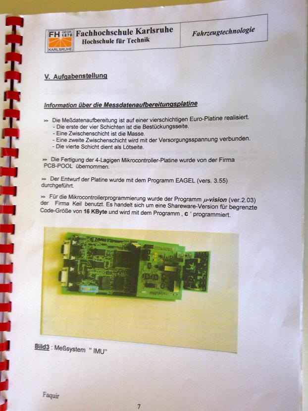
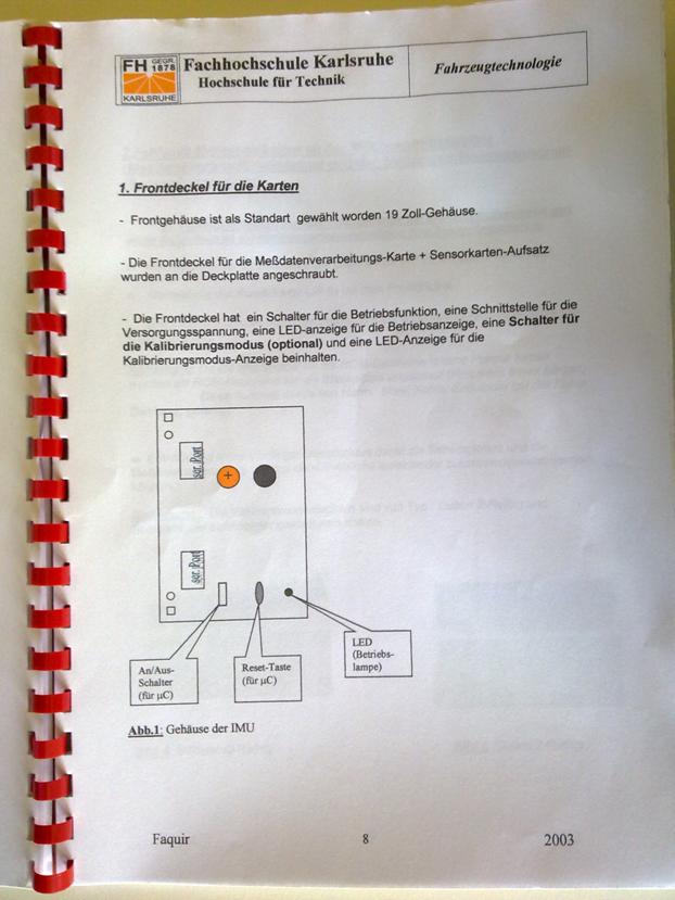
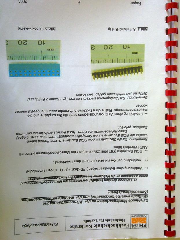
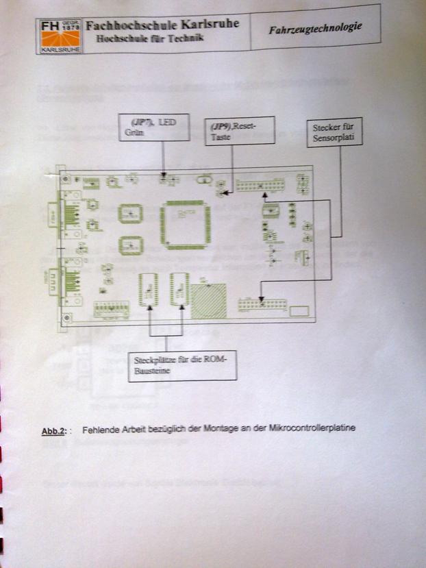
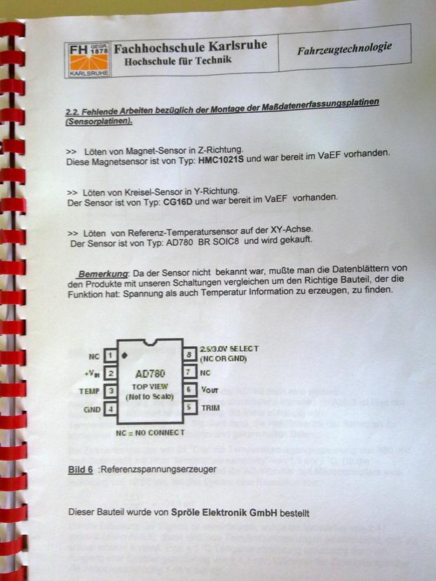
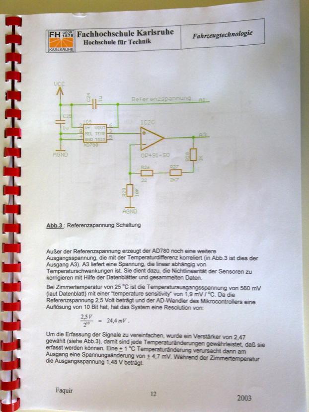
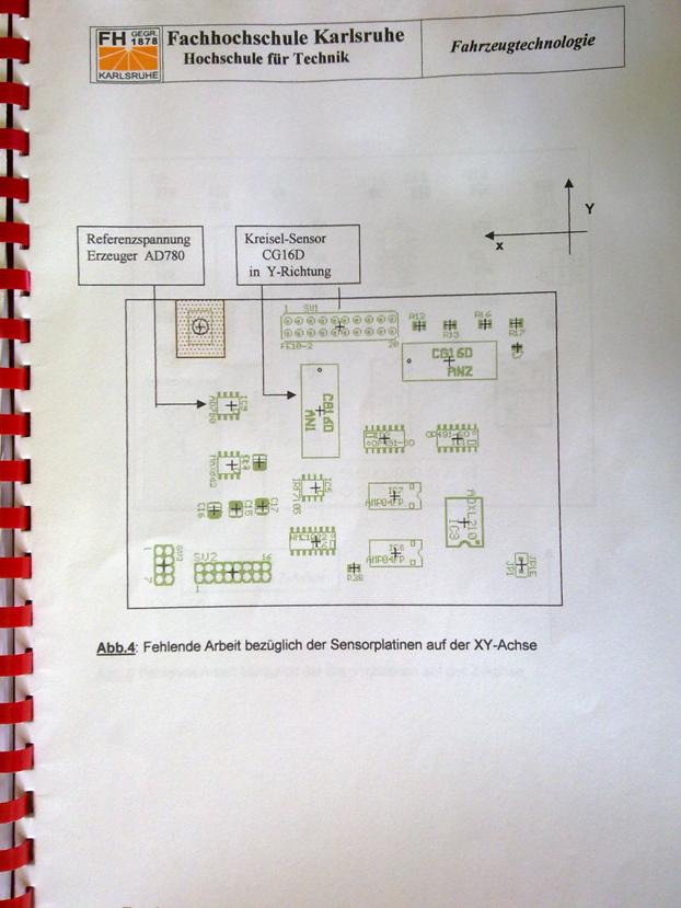
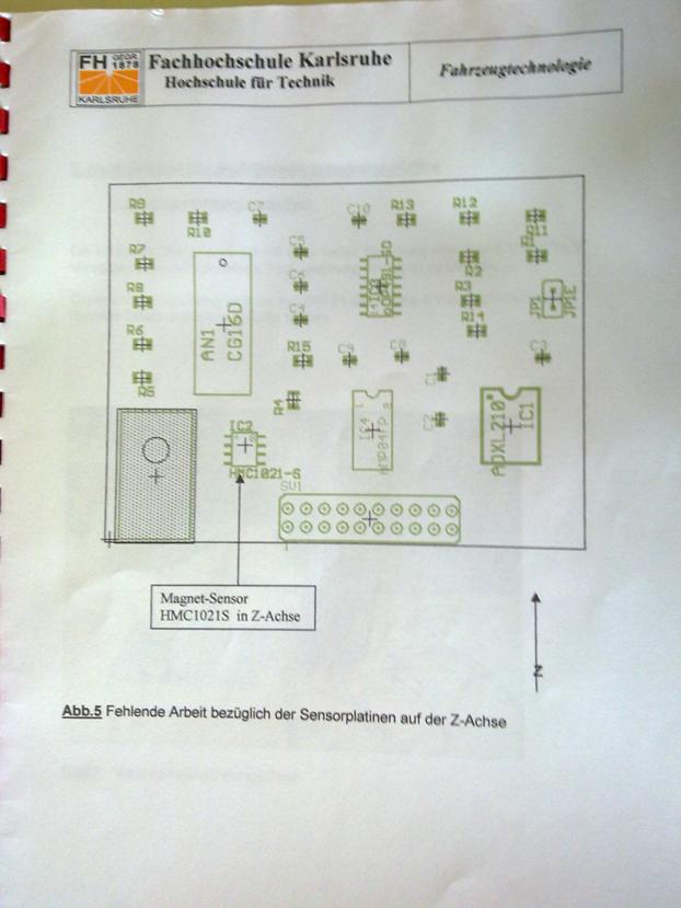
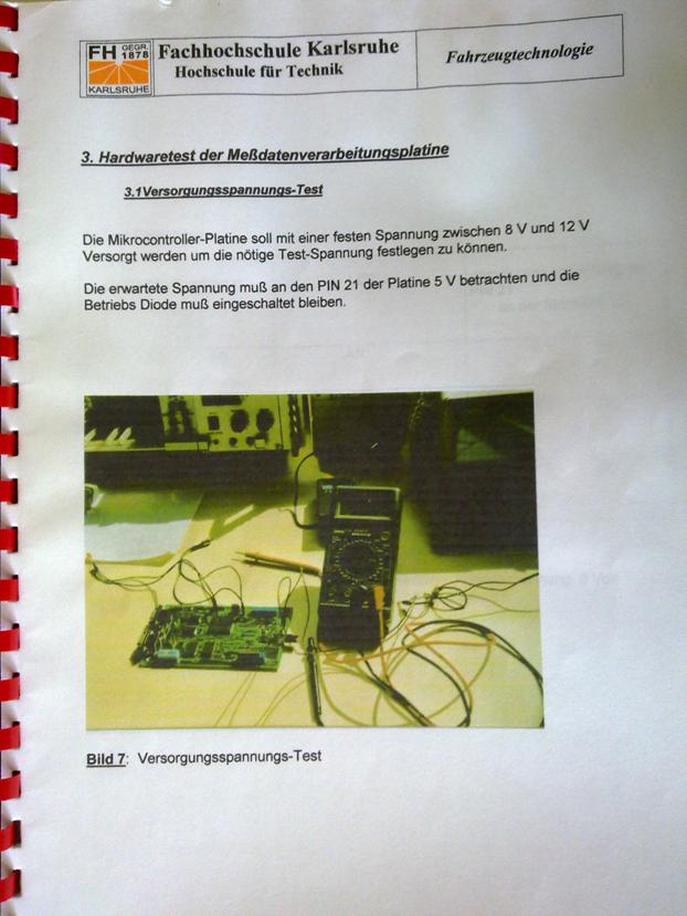
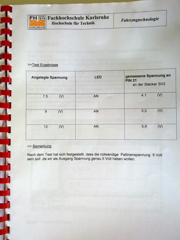
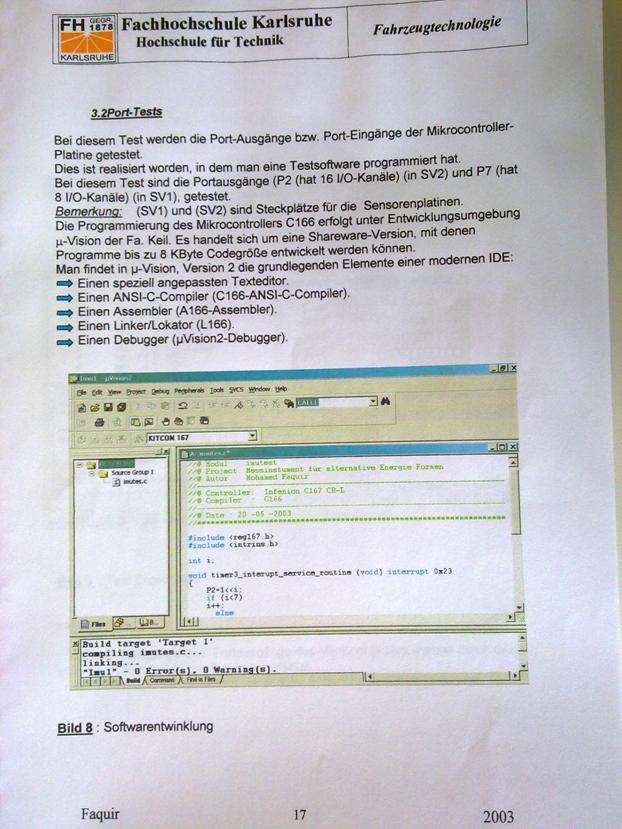
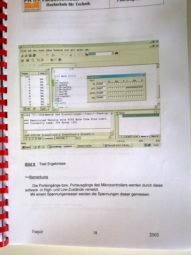
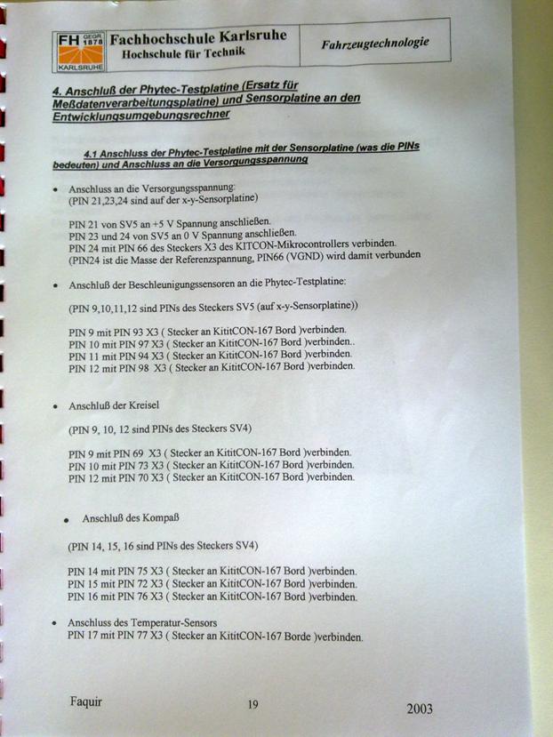
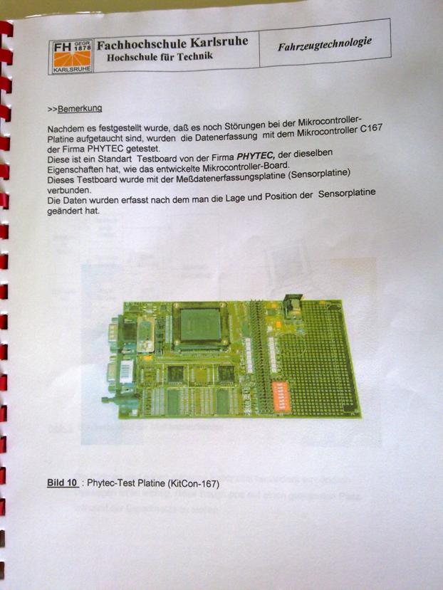
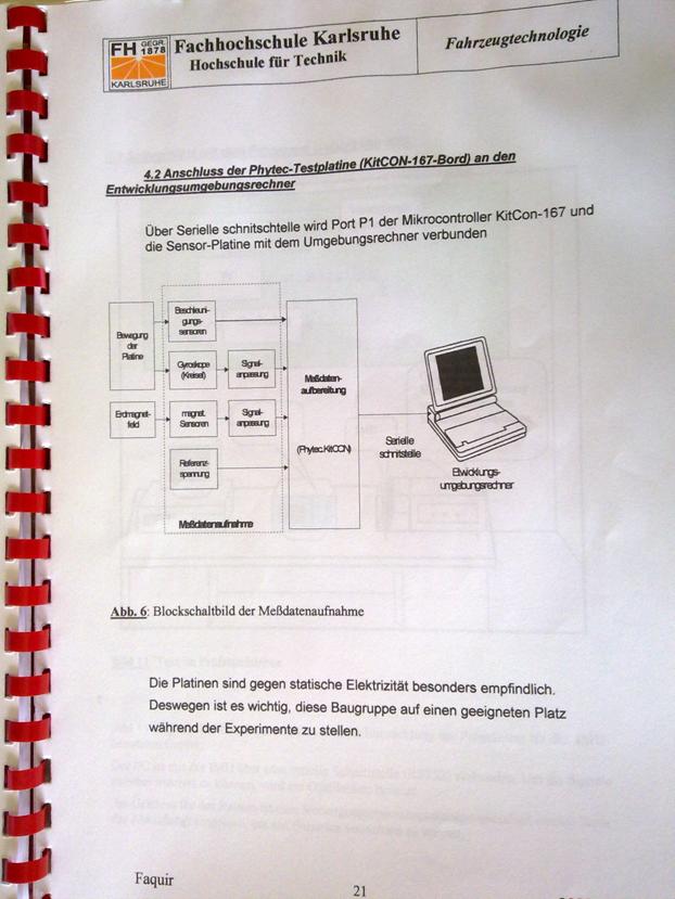
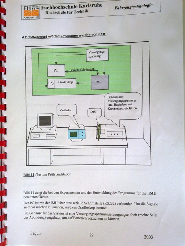
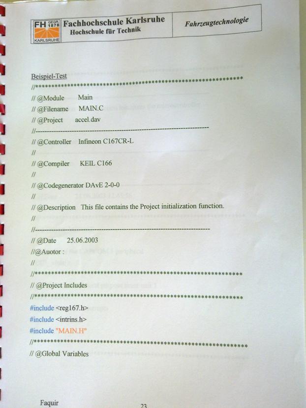
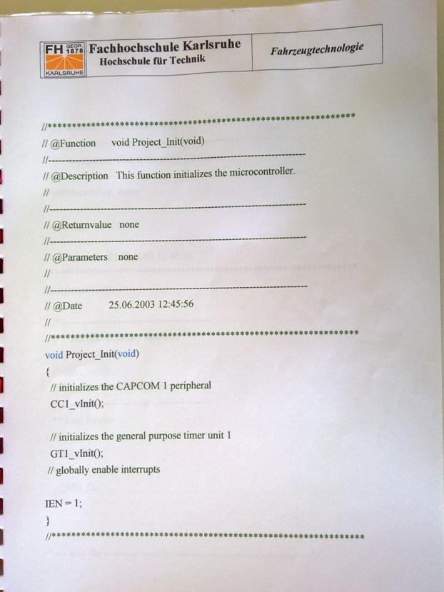
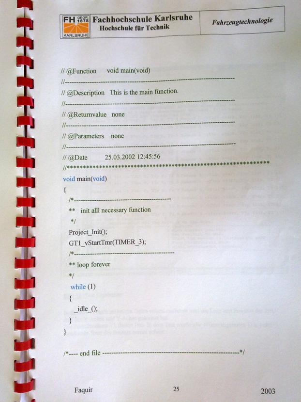
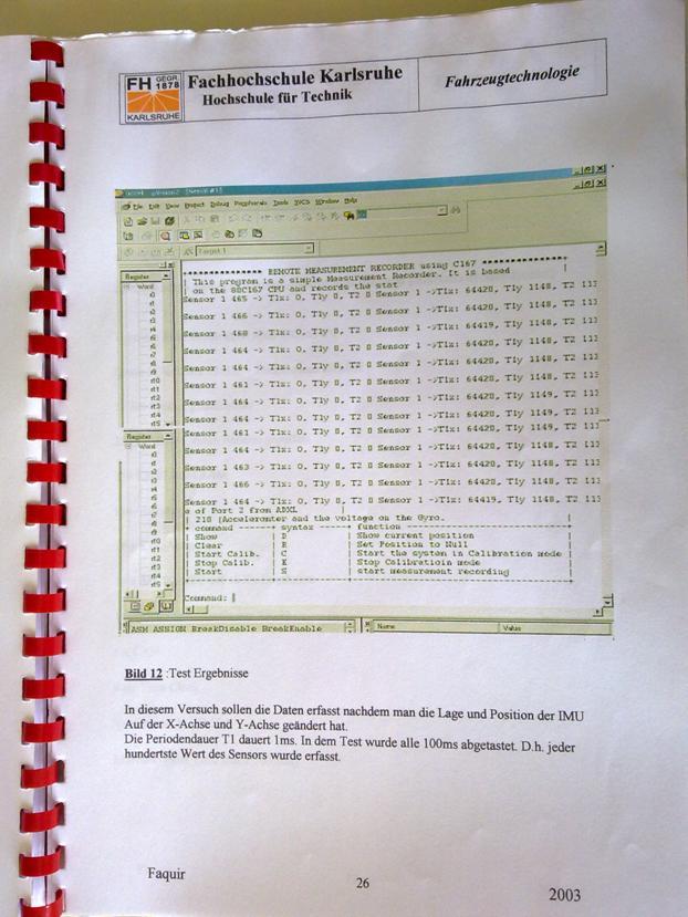
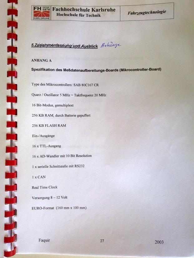
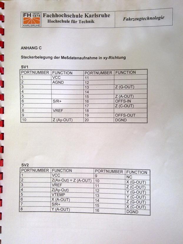
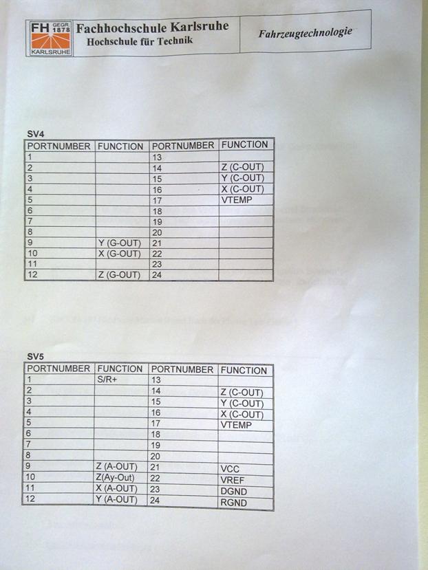


Based on Mohammed Yassir Mikou,
"Integration und Test eines Board-Computers f�r ein alternatives
Luftschiff", Master Thesis (Diplomarbeit)
This work deals with the development of software for controlling an
airship, the weather data (solar radiation, temperature and wind) to determine. The aim of this
thesis is to integrate control cards, ie To allow
communication between the Sensors, Actuators and transceiver card. The
integration should be carried out as part of a Linux platform. It has gained
acceptance because of the embedded system and the specific processor type, the
RedHat distribution.
TABLE OF CONTENTS
List
of Figures ........................................................................
2�����������������������
LIST
OF TABLES .............................................................. 2�����������������������������
1.
Introduction
to the airship project ..................................... 4����
1.1 . �� The Lotte-project and the "Alternative LOTTE"
............................... 4����
1.2 . �� Development method
............................................................................ 4������ �����������
1.3 . �� Activity and REALISIERUNGSANNaeHERUNG ...... 5���������������������������
1.4 ���� Overview
................................................................................................
5���
2.
Basics of Work
........................................................... 6�������
2.1 ���� The V-model
............................................................................ 6
2.2 . �� Structured Analysis (SA) /structured design (SD) ............. 8���������������������
3.
Development environment
..... 10�����������
4.
Architectural design, and implementation ..................... 11���
4.1
. �� The implementation of the
BASISSTATIONSPROGRAMMS ...................... 14� �����������
4.2 . �� The implementation of the LUFTSCHIFFPROGRAMMS
............................ 15��
Section 4.2.1 , �������������������������������������������������������������������������������������������������������������������� the
sensors
........................................................................................
16�������������������������������������������������
4.2.2 . ���� The actuators ...........................................................................................
17����
Point 4.2.3 .. � The
Transceiver
.................................................................................................
18����������
Point 4.2.4 .. � The Board
Computer ........................................................................
20��
5.
Operating System Installation
.............................................. 22�����������
5.1 . �� Problem
...............................................................................
22�
5.2 . �� ..................................................... 22
implementation of the installation
5.2.1 . . �� configuration
of the core ..................................................................
23����������
5.2.2 . . �� Modules
creating and installing
......................................................... 38������
5.3 . �� ..................................................................
39 development environment������� �����������
5.4 . �� .................................................................................................
41 Real�������� �����������
5.4.1 . . �� latency
and fluctuation
........................................................................ 42������
Item 5.4.2 above . ��������������������������������������������������������������������������������������������������������������� hard
and soft real-time conditions .............................................. 43���������������������������������������������������������������
5.4.3 . . �� embedded
applications ...... 46������������������������������������������������������������������������
5.4.4 . . �� Installation
of Linux-Echtzeit
................................................................ 47����
6.
Description of PORTZUGRIFFSARTEN .......................... 49����
6.1 . �� Direct Access
...............................................................................
49��
6.1.1 , ���� .............................................................................
rights awarded 49����������������
6.1.2 . . �� Einlesen/Ausgeben
...............................................................................
51�����
6.2 . �� ACCESS about
GERaeTEDATEIEN ............................................................ 54����������
6.2.1 ), . � Ports Opened
and closed ..................................................................
54��������
Item 6.2.2 , . �� canonical
and non-canonical Input/Output ......................... 56����������
6.2.3 . . �� synchronous
and asynchronous transfer ............................................ 67��
6.3 . �� THREADPROGRAMMIERBEISPIEL
............................................................ 72������� ������������
7.
...............................................................................
75 LITERATURREFERENZ�������
2
List of figures:
Figure 2- 1: V-model [ 1]
....................................................................................................
6 ����
Figure 2- 2: SA/SD [4] ...
9
Figure 4- 1: The connections of the system
................................................................... 12 �
Figure 4- 2: overall system of the "alternative
Lotte" .................................................. 13 ����
Figure 4- 3: Diagram of the correlations
............................................................ 14 ���
Figure 4- 4: airship as
embedded system
................................................................ 15
Figure 4- 5: : The
sensors through the serial interface with the Board
Computer 16 connected ..... ��������
Figure 4- 6: The
actuation system through the serial interface to the Board Computer
Angeschlossen................................................................................................................... ��������
Figure 4- 7: The
transceiver through the serial interface with the Board
Computer 18 connected ..... ��������
Figure 4- 8: Graphical User Interface
.......................................................... 19 ���������
Figure 4- 9: The Board Computer
................................................................... 20 �������
Figure 5- 1: make config(1 Option: Code maturity
level) .... 24 �������
Figure 5- 2: make config(2 Option: Loadable module
support) .............................. 25 �����
Figure 5- 3: make menuconfig(1, half of the
Optionen) ............................................ 25 ����
Figure 5- 4: make menuconfig(2, half of the Optionen)
............................................ 26 ����
Figure
5- 5: make xconfig(everything on Einmal)
............................................................... 27 �������
Figure 5- 6: Option Processor type and features
............. 29
Figure 5- 7: Call the assistance of the submenus
Processor family .............................. 29 ��������
Figure 5- 8: sub-menu (CPU frequency scaling) from
option 3 .............................. 30 ����
Figure 5- 9: General setup(1, Haelfte)
........................................................................
31 ������
Figure 5- 10: submenu
PCI Hotplug support .......................................................... 31
Figure 5- 11: submenu PCMCIA/CardBus support
................................................ 32 �������
Figure 5- 12: 42 The Ereignislatenz
................................................................................... ����
Figure 5- 13: periodic fluctuation
........................................................................ 42 ��
Figure 5- 14: Schadensaenderung in dependence of the
response time ............. 43 ���
Figure 6- 1: Terminal E/A-functions in the Overview
.................................................. 66 ��
Figure 6- 2:
asynchronous data transfer with 7 bits Datenlaenge .........................
68
LIST OF TABLES
Table 5- 1: Comparison
of the performance of Linux with the commercial Echtzeitkernen.
................................................................................................................................
Table 6- 1: macros to
access I/O-Ports ............................................................ 52
Table 6- 2: The five different Modi-Eigenschaften a
terminal ................ 61 �
Table 6- 3: Possible Steuerzeichenvarianten for the
non-canonical input .... 63 ��
Table 6- 4: POSIX-functions to query and change the Terminalattribute..66 �����������
3
Thanksgiving
This thesis
was developed at the Association for alternative energy research in Karlsruhe in cooperation with the University
of Applied Sciences in Kiel. At this juncture I
would like to thank for Prof. Dr.
-Ing. habil Albrecht to, this thesis by the University of Applied
Sciences and betreuet has had so much patience,
and I would like to thank Mr Ing. Murad, Samir for the enabling of the thesis
and the furnishing of the laboratory with its entire Hardwareinhalt thank
you.
My special
thanks to the German state, has given me the opportunity to continue my
education and to acquire new perspectives.
Last I
would like to thank my parents, stood side by side to me, despite the distance,
and with my friends, the me morally and actually have supported.
At the
Institute of statics and dynamics of the air and Raumfahrtkonstruktion at
the Universitaet Stuttgart was built a Solarluftschiff in February
1992 the project "Solarluftboot" initiated and the purpose of this
project was, new materials, new methods and a new concept for the control to
develop an airship, the is operated by a Solarenergiemaschine.
The
"Alternative Lotte", a joint project of the VaEf e.V. , the
Universities of Karlsruhe and Stuttgart and Karlsruhe University of
Applied Sciences, was planned as an experimental airship, it is to be
controlled directly from the ground (first step of the implementation) or
automatically to specified coordinates (the second step of the implementation)
fly, the energy will be the first step guaranteed by conventional batteries,
but it is planned, and later to switch to solar power, with the
"alternative Lotte" specific data will be during the flight through
collected different sensors (sensors), the on the airship can be installed in
the first step is the speed of the wind, the temperature and the solar
radiation measured. In addition to such a flight data, such as angular velocity
and acceleration are navigational to azimuth angle measured.
1.2
. Development Method
The complete system of
the airship was in a laboratory with a Board Computer, and a sensory system-, a
actuators and a Transceiverkarte provided as embedded system.
The Software is with the
C-programming language developed under Linux, the complete development process
follows in general the well-known V-model.
5
1.3
. Activity and Realisierungsannaeherung
The task is to provide a
software interface for the communication to develop, the on the board computer
running, which in turn with the three hood (sensors, actuators, and
transceiver) is connected on the airship, the purpose of this program is, the
communication between the sensors and the motors and the transceiver on the
"alternative Lotte" sensor platform to produce, the sensors is used
to the solar radiation, and the speed and the direction of the airship to
measure and the data to send to the board computer, the actuation system is to
control the direction and the acceleration (speed, position) of the airship
(engines) used by the data from the Board Computer dependent on the data
received from the sensors will receive the Transceiverkarte is used, to the
data in the A direction by the Board computer to send to the local computer
and, in the other direction to receive from the local computer.
So the thesis can be
divided into the following tasks:
9 Preparation,
configuration, and translation
of the core.
9 Installation
of Linux and real time extension.
9 Programming
of the communication protocol between the cards and the Board Computer with the
C-programming language.
1.4 Overview
After a brief
introduction in a concise form is basic knowledge of the given development
methods used.
The V-model, and some
general information about (SA/SD) are in Chapter 2 gives. Chapter 3, there are
a impression of what tools have been used in 4 chapter is a detailed
description of the full system, Chapter 5 discusses the operating system and
the real, Chapter 6 provides the necessary information on the serial interface,
as well as the approach to the programming and the tests that have been carried
out to the functionality of the system to check.
6
������������������������
The development is on a
computer with GX1-AMD K6 300MHz Processor, 32MB RAM, 16 MB Flash Disk is done
by the hardware (hood) to each other with the Board Computer was connected via
R232 order.
The following are
software tools for the development have been used:
9 SUSE and RedHat Linux.
9 KDevelop:
C/C++ development environment under Linux.
9 "GCC"
and "GDB" Compiler and Debugger for C-programs under Linux.
9 Microsoft
Word to word processing and the representation of the design structure.
9 Two
computers each with a RS232 connection for testing purposes.
9 Null
Modem Cable for the connection of the RS232 serial interfaces.
9 Hyperterminal
under Windows and minicom on Linux.
11
The task is to provide a
software interface to develop to the integration with integration is the
communication between the control cards, i.e. the sensors, the actuators, and
the transceiver, this Communication is to be in the form of a C-program take
place on the board computer, the then the exchange of data between the control
monitors and controls, these four components are located on the "Alternate
Lotte" and will be the serial interface connected to each other.
Each of these hood was
for either as a thesis,
Thesis or Ingenieurpraktikum designed, developed, and tested ���������������������� - up on
The Board Computer, of the company Arcom was
purchased �������������� [
5]. The Cards
Each contain a
microcontroller, the RS232 serial data for either to send provides or is ready
to data from RS232 to receive.
The sensor collects data
and sends it to the Board Computer go, it will be the Sonnenstrahlstaerke,
speed and direction of the airship measured (sunlight in dependency of the
coordinates and the season), for example by sensors be used for each
coordinate: X-direction, y-direction, and z-direction (the temperature, angular
velocity and azimuth angle will also be identified).
The actuation system is
used to control the operation of the "alternative Lotte", i.e. the
direction, speed, and angle indicate, dependent on the information from the board
computer, either the then this data from the sensors or but from the
transceiver receives.
For its part the
Transceiverkarte to the exchange of data between the "Alternate
Lotte" guarantee and the ground station and wireless, by a modem for use
with an antenna, this has already been successfully tested, since the
Transceiverkarte via a graphical user interface, it is possible, commans
manually from the ground and enter corrections.
 12
12
The full system
connections between the hood with the airship and the ground station
(Benutzerschnittstellencomputer) are shown in the following figure:
Figure 4- 1: The
connections of the system.
The figure describes
both the connections between the board computer and the three hood (sensors,
actuators, and transceiver) in the "alternative Lotte" as well as the
connection to the computer in the ground station.
Similarly, the figure
shows that the overall system is divided into two parts:
1. The
ground station: with a computer, of the airship from the ground and can control
monitored. For this task is a graphical user interface uses. This GUI
hardwaremaessig accesses to the
13
Transceiverkarte back.
The transceiver in turn is based on a modem, the other with a wireless modem on
the airship (by antennas) data in both directions may or should replace. By
this graphical user interface it will be possible, wind speed, solar radiation,
temperature, Luftschiffgeschwindigkeit Luftschiffkoordinaten or to receive and
at the same time in the other direction wind speed, acceleration, and azimuth
angle to send.
2. The
airship: Here is the actual task of the present work, the integration of the
three hood in the embedded computer, this is a null-modem cable by each
connected with the hood, the embedded computer contains four serial interfaces,
and the hood itself, are at least equipped with a serial interface. In the next
section will be discussed in more detail the individual cards or
presented.
Figure 4- 2: overall
system of the "alternative Lotte".
4.1
And The implementation of the Basisstationsprogramms
Figure 4- 3: Diagram of
the correlations.
9 The
display is the screen of a computer in the ground station, it is used to to
observe the received data gathered by these data gathered by the sensors are in
the "alternative Lotte" detected.
9 The
keyboard is used by the user, to write to the commands, the he to
"alternative Lotte" wants to send commands to the "alternative
Lotte" sent by the serial interface, whenever the user commands to
"alternative Lotte" wants to send, will be the data to the Board
Computer passed from the transceiver.
9 The
serial port, the peripherals between the user interface and the "Alternate
Lotte". By we use the user interface, we can tell, that the user receives
data (from the "Alternate Lotte") and data or commands (to
"alternative Lotte") sends.
9 The
added security layer is the communication protocol, the commands that the
ground station to "alternative Lotte" send, will be confirmed, if the
confirmation predictions, the commands are returned.
15
4.2 And The implementation of the
Luftschiffprogramms
Figure 4- 4: airship as
embedded system.
16
Section 4.2.1 The sensor
system.
This card is one of the
most important components of the "alternative Lotte". The sensors
monitor the overall system, the fact that sensors are attached to this card,
which capture the acceleration, the speed, the coordinates (the position of the
airship), the angular velocity, the azimuthal angle and the direction of the
then to the Board Computer via the serial interface will be transferred, this
in turn, sends the data and/or information wirelessly to the ground station go.
In addition provides us with the sensors other data, such as the solar
radiation (solar radiation, and wind) and the temperature.
Figure 4- 5: : The
sensors through the serial interface with the Board connected to your computer.
17
4.2.2 . The
actuators
The sensors allows,
flight information to collect, to bear the Veraenderlichkeit of the data to be
able to be used must be the actuation system, i.e. the control card contains
e.g. a stepper motor and a servo motor, in order, on the one hand, the speed of
the airship and, on the other hand to control the direction, the motion and by
the Board be Flugelbefehle received to your computer, these commands are either
from the sensors or from the ground station and then the board computer made
available to the actuators.
Figure 4- 6: The
actuation system through the serial interface with the Board connected to your
computer.
18
Point 4.2.3 .. the
Transceiver
This map consists of
both hardware and software, the hardware is in the form of a modems, the
wireless communication between the local computer to the ground station and the
board computer, on the "alternative Lotte" guaranteed. This
communication means data exchange between the ground station and the airship,
by a graphical user interface (the software p. Fig. ?) is made available, in
order, for example enter the speed, this is by the Board Computer and forwarded
to the actuators according to the speed increased or lowered, depending on which
value has been entered or what is better.
Figure 4- 7: The
transceiver by the serial interface with the Board connected to your
computer.
 19
19
If the transceiver is
receiving data gathered by the Embedded System, these data will be (in the
Receive Data frame displayed) to the ground station with a frequency between
433.200 and 434.775 MHZ sent, and the same happens when the transceiver data
from the ground station to the "alternative Lotte" and then send the
actuators wants to (in the other direction you send commands by sending the
data frame is written).
Figure 4- 8: Graphical
User Interface.
 20
20
Point 4.2.4 .. The Board
Computer
The Board Computer is
the embedded computer in the "alternative Lotte". This computer
closes the three hood through the serial interfaces (RS232 together.
Specification of the embedded computer ��� [ 5]: EBX AMD Geode� GX1 Embedded
Computer
The SBC-GX1 is a low
profile, without fan, the EBX Format board, is based on the 300MHz
MMX-increased AMD Geode GX1 processor, it includes all
Rechnerstandard-Schnittstellen and a full range of Multimediaeigenschaften:
VGA-screen (National XpressGraphics), Ethernet 10/100BASETX (PCI 2.1
compatible), integrated 16Mbyte FLASH, double-USB, compatible interface of the
sounds and four serial interfaces.
Figure 4- 9: The board
computer.
Processor
Memory
Cache��������������������
Video
Without fan, Pentium
class, 300MHz AMD Geode� GX1
SDRAM 144-pin SODIMM
socket low-profile, 256Mbytes Max.
Flash: 16Mbytes Intel
strata Flash
SRAM: 128K battery
backed (factory fit option) 16k L1 write-back cache
TFT flat panel & CRT
XVGA, 1 - 4MB SDRAM video memory
Drive Support FDD, HDD, Silicon
Disk in Flash, Compact Flash
Networking Support 10/100BASETX
Ethernet via RJ-45
USB interfaces
I/O Interfaces
PC peripheral
Additional I/O
Watchdog timer
Enlargement
Sound��������������������
BIOS
MTBF
Format
2 X USB ports (USB 1.1 )
4 X;
16550-compatible fast serial ports (3 x RS-232, 1 x RS 232/422/ 485)
Keyboard, Mouse, Printer Port
8 General
purpose digital I/O signal and two user defined Jumper
Real Hardware Watchdog
(2 or 8 seconds) with Reset output.
Compact Flash socket,
PC/104 bus, PCI slot 16-bit SoundBlaster/Per compatible interface Award BIOS
(in accordance with Millennium)
90.000 Hrs
EBX format, size 5.75
" x 8.00 " (146 mm x 203 mm)
Power Requirement +5V only for
operation (@ 1.5A Type)
Temperature Range
From: -20 to 60 �C
processor fed with a low profile (no fan) temperature drop.
22
5. �� Operating System Installation
5.1 Problem .
The Board Computer hood
is to manage the communication between.
He comes from the
company Arcom [ 5]. on him is no operating system installed, since
only
A 16MB Flash Disk is
present (embedded computer), it is useful, to use Linux as the embedded
operating system, Linux offers the advantage that the core (the core of the
operating system) can be created the desired configuration of. This saves space
on one hand, on the other hand, the system or the hardware be optimally set
up.
5.2
Implementation of the installation.
At the beginning of the
configuration options were the most disabled, because only a small core as soon
as possible or a general operating system was needed, the following options
were disabled: Parallel support, Plug and Play configuration, Enterprise Volume
Management System, multi-device support (RAID and LVM), cryptography support
(CryptoAPI), networking options, Telephony Support, ATA/IDE/MFM/RLL support,
SCSI support, Fusion MPT device support, IEEE 1394 (FireWire) support
(experimental), I2O device support, network device support, amateur radio
support, IrDA (infrared) support, ISDN subsystem, Input core support,
multimedia devices, sound, USB support, Bluetooth support, kernel hacking,
library routines, plug in CPU scheduler that support resource management
modules and build options.
In total, 33 options are
disabled, they were divided in part, in several sub-menus, and also partly in
only in a single sub-menu, and the majority of options contained two to three
sub-menus, and the pictures show some screenshots, which an impression of the
number of options is to communicate.
In this way although the
configured core is small, did however, he is only after some effort
compiling.
Due to the large number
of submenus in peace had to be considered options, so that you can be more
clearly understood.
23
The configuration steps
are available everywhere on the Internet, however, the configuration of the
core is not comparable with the installation of Windows, and even people, the
experience with the installation of Linux, had difficulties with security with
the core configuration.
The following examples
are intended to illustrate Embedded operating systems, such as embedded
operating systems such as PDAs, organizer, and mobile phones present, including
WindowsCE or embedded Linux but also on this hardware is not, for example hard
disk, but only a Flash Disk, on which the operating system is charged.
The installation of the
core is actually a sequence of six commands. It is the first command the One
who, of the most processing time takes or configuration in. The other need
then depending on computational power and memory up to a few days processing
time.
These commands are as
follows:
� Make menuconfig
� Make DEP
� Make bzImage
� Make modules
� Make
modules_install
� Configure the boot
loader.
5.2.1 . . configuration of the Core
Only the administrator
(root) or the user, which these rights were granted, the appropriate access
rights to perform this configuration, this is done with the command sudo
"command", previously the administrator must the user all rights in
the file /etc/sudoers assign.
If the Kern-Quelldateien
are not yet installed, this should be done as the first, because otherwise the
configuration does not can be started, the present source files were 208.19 MB
in size, and also the Help files are included in the directory
/usr/src/linux-2.4.21.99 /documentation.
24
There is a big help file
with 1.2 MB for the core configuration, and each small help files to almost
every option.
In order to now in the
correct directory ( /usr/src/linux-2.4.21.99 in this case) one of the three
possible enter commands, there are far more than 1,000 options to choose from,
with these options you can influence, which functions directly be integrated
into the core, which as a module and which are not available to:
- Make
config: a couple with Y(yes) /N(No) or M (modules) to answer questions one at a
time (P. image. ? and ? ), without the
Possibility to have,
reenable remote access or umzuaendern (textbased),
EN
few questions previously answered questions hangs up with together!
Figure
5- 1: make config(1 Option: Code maturity level).
25
Figure 5- 2: make
config(2 Option: Loadable module support).
- Make
menuconfig: is also text-based in the process, there is also the opportunity,
before and reverse to jump and to correct, i.e. , the initially to make
amendments reenable remote access to edit or even new (see image, 5.3 and 5.4
).
Figure 5- 3: make
menuconfig(1 half of the options).
26
Figure 5- 4: make menuconfig(2
half of the options).
- Make
xconfig: is not more text oriented, but simply can be operated with the mouse
(see image, 5.5 ), (xconfig only if the programming language Tcl/Tk is
installed), but they will need the X11-surface, i.e. the necessary libraries
and the support for the Graphical User Interface, or KDE, and that is why this
alternative is usually only at the beginning to test and/or used learning, one
hand, because the core is compiled only for this reason, to a minimum to ensure
demand for storage space, so this is not a recommended alternative, unless you
want to compile the core to its Linux distribution (Suse, RedHat, �) to its
special requirements of hardware and security to adapt and optimize. without
sufficient basic knowledge can play a to the configuration of the core the
existing installation or even make the whole system unusable.
 27
27
Figure 5- 5: make
xconfig(everything all at once).
After menuconfig has
started, there are options to the "Y" for Yes or "N" for
"no" to answer Are, partly you can with "M" for module
answers, and in some cases, values are specified.
First, one should the
current configuration under a different name save as a precaution, the last
option: Save Configuration to alternative file), as it can happen that
the changes in the preconfigured file be
stored, which can lead to problems, if the file does not compile due to e.g.
Unvollstaendigkeit cannot be, i.e. it comes to the problems of the Kernladens
when the computer is restarted.
What are modules and
their benefits?
A module may be, in so
far as is necessary, be integrated into the core, these modules are available
but only then, when the core is loaded, loaded to the core modules can be
unloaded or which modules are trying to start to find your hardware
(autoprobing).
When the computer is a
Basiskern loaded, the contains only those functions to Start are required,
these belong firmly to the core, if in the current operation functions will be
needed (e.g. , for the new hardware), is the required code as a module
connected to the core, and if this
28
Additional functions not
a while more will be needed again the module can be removed from the core, this
modularized approach has many advantages:
� Kern-Module
can be integrated as needed, and if a specific module only rarely is needed,
can be saved on this memory, i.e. , the heart of the matter is not greater than
is essential, and to the hardware of the optimally adapted user.
� For
a change of the hardware (such as a new
network card) must be compiled no new core, but only the new module will be
involved.
� In
the development of a Kern-Moduls constantly of the computer must not be
restarted in order to made to test changes to the core.
It is enough, to
recompile the module, then there it can be tested while the system is
running.
Under the Options, you
will find for example, physical resources, such as drives, serial/parallel
ports, Audio, and Videogeraete, network interfaces, keyboard, mouse, etc�
1.
Code
maturity level options: here you have the possibility, even the Core���������������������������������
Components that are not
yet mature as apply, in the kernel config file
To be taken into
account, in the other case, these options will not be active, or are not
displayed. This option was chosen, as a module cannot be you are not
elect.
2.
Loadable
module support: you determine whether this modularized ���������������������������������
Concept supports,
whether or not some of the options as loadable modules must be available or
only with Yes/No the core are to be tied.
3.
Processor
type and features������� (p.
image. 5.6 ): Here you have the type of processor
Specify what the speed
and size of the Code will affect.
Code in this case is on-, but not ������������ - as usual - abwaertskompatibel
(p.
Image. 5.7 ), e.g. , a
K6-processor can a K7-processor support
29
But not vice-versa, here
was an Athlon/Duron/K7-processor was elected.
Math emulation and
symetric-multiprocessing support were not elected,
Figure
5- 6: Option Processor type and features.
Figure 5- 7: Call the
assistance of the submenus Processor family.
30
Figure 5- 8: sub-menu
(CPU frequency scaling) of Option 3.
4.
General
setup: Networking support � (see
image, 5.9 and 5.10 ): This option
In any case it is
needed, since some internal commands to build the network protocol, the correct
networking options are only for item 13 (Networking options) discussed PCI
support was chosen (p. image." field 5.11 ), on PCMCIA/CardBud support (see
image, 5.12 ) has been omitted, SystemV IPC had to each case because of the
needed inter-process communication are selected in the programming, Elf and
a.out Kernel Core format are also set to "yes", Power Management
Support for laptops with "yes" answers, but answered in ACPI
support.
31
Figure 5- 9: General
setup(1 half).
Figure 5- 10: submenu
PCI Hotplug support.
 32
32
Figure 5- 11: submenu
PCMCIA/CardBus support.
5. Binary emulation of other systems: This
option is necessary, in order to e.g. ����
SOM and/or
Solaris-binaries to load and implement directly. SOM is a binary
executable format, the HP/UX is accepted, this option has been omitted.
6. Memory Technology Devices (MTD): so are
e.g. Flash, RAM meant. ���������
They are mostly for
stable systems used in embedded systems, and that is why this option is very
important in the present case and had to be answered with "yes" to
any partition was selected, because only a Flash Disk is present, and even the
Flash Disk of Arcom is the company to enable specified here-the driver for the
SBC-GXn Board-Familie has also enabled.
7.
Parallel
port support: here it is to the parallel port to the ����
Normally, the printer is
connected, in the present case, it is not planned to use a printer,
therefore, it was "no" selected.
8.
Plug
and Play configuration: is a standard for plug-and-, the ������������������������������������������������������������
In the Detection address
decoder unit can be configured.
9.
Block
devices: a floppy drive in the present case is not �����
Needed, a
RAID-controller also not normal (not SCSI) hard drives and CD-ROM drives (among
other things) are under Linux as a block devices detected.
33
10.
Enterprise Volume Management System: this is a
plugin-based �����������������������������������������������������������
Framework for
Datentraegermanagement and combines the support for the partitioning, software,
RAID, LVM, and much more in a single interface, user tools are necessary to the
administration of EVMS logical magnetic media, according to this option was
enabled.
11.
Multi-device
support (RAID and LVM): RAID and logical volume ����������������������������������������������������������
Management will be in
our Board Computer not needed, so if the "No" option was
elected.
12.
Cryptography
support (CryptoAPI): the authentication and guaranteed �����������������������������������������
The encryption and
probably the encrypted authentication and transfer over the network (no help), according to, a
"no" selected.
13.
Networking
options: Network packet filtering is responsible for the firewalls. ��������������������������
In this project you are
not needed, so "no" selected, select the TCP/IP networking was
answered with "yes".
14.
Telephony
Support: was not elected, for the case that phone ��������
Should be, must be a
connected-associate.
15.
ATA/IDE/MFM/RLL
support: here offers the possibility to appliances to ��������������������������������
Support to the IDE-bus
be connected such as IDE-disk drives and ATAPI CD-ROMs.
16. SCSI support: Support for the SCSI hard
drive is not necessary.
In contrast, the option
SCSI CD-ROM with answers "yes". SCSI low-level drivers should not be
supported, as other SCSI-hardware not is present.
17. Fusion MPT device support: the option
Message Passing Technology Offers
As a machine name
matches the possibility to activate a Systemhost
34
Either as a
high-performance SCSI Host initiator or as a LAN (but not with parallel
SCSI-media). The Fusionsarchitektur is in the location, these protocols
bi-directionally in Hochgeschwindigkeitslaser (up to 2GHz * 2ports = 4GHz) and
parallel SCSI (up to Ultra-320) Physical Media process. These drivers need a
Systemhost installed in the MTP-compatible PCI-adapter, these adapters contain
special I/O processors, and thus was the option to "no"
answers.
18. IEEE 1394 (FireWire) support
(experimental): Fire Wire-Geraete are not
Present, therefore the
fire Wire-Anschluss are not supported.
This option would be for
example inactive, if the first option(Code maturity level) answered with a
"no" would have been, because the FireWire under Linux to the core
2.4 has not yet been declared for maturity.
19.
I2O
device support: Is a intelligent input/output architecture that it ��������������������������������������������
Allowed, hardware
drivers in two shares to parts: the OS module (OSM) and a hardwarespezifisches
module (HDM), but it needs a I/O and in the Computer
Schnittstellenadapterkarte. This card contains a special I/O processor, the
high speed creates, because the CPU is no longer with the I/O needs employ,
because the I/O Schnittstellenadapterkarte is not present, "no"
selected.
20.
Network
device support: If you are in any way with another ����
Computer wants to
communicate, then this is the first option (network device support) with
"yes" to. In the track, the kind of communication and the hardware be
specified, all of the following submenus were answered with a "no":
ARCnet devices, Ethernet (1000 Mbps), FDDI driver support, HIPPI driver support
(experimental), wireless LAN (non-hamradio), TockenRing devices, Fiber Chanel
driver support, Red Hat Creek Hardware VPN (experimental), WAN interfaces. In
contrast, PPP (point-to-point protocol) support, SLIP (serial line) support set
to "Yes" under the Option Ethernet (10 or 100Mbit) were the
information on this network card in the affirmative.
35
21.
Amateur
Radio Support: This can cause the computer communications via ������������
Amateur radio operations.
One of these protocols can be either for point-to-point or as a institution for
TCP/IP will be used, the option has not been in the affirmative, since first,
no appropriate hardware for this is present, and secondly not on the radio with
other computers to communicate.
22.
IrDA
(infrared) support: Here you can find drivers for the infrared port. ����������������������������������������
This is not needed,
according to the option has been denied.
23. ISDN subsystem: here are drivers for the
Linux supported hardware
And options for various
ISDN-apparatus compiled, therefore these options were answered with a
"no".
24.
Input
core support: Human Interface Device (HID) refers to a ��������
Certain Geraeteklasse
the USB-standards for computer, with the description are described such devices,
the directly "interact with people". meant are apparatus, with which
the user directly communicate with the computer, such as mice and keyboards,
but also gamepads, tablets and joysticks, HID-Geraetetreiber are usually
included in the major operating systems, is a HID device (during operation) is
connected, it is usually directly as a type Eingabegeraete (Human Interface
Devices) recognized and then displayed in the Device Manager, support for such
Eingabegeraete is not needed and therefore "no" selected.
25. Character devices: In order to anything at
all to be displayed on the Monitor
Have the first two
options (virtual terminal & Support for console on virtual terminal) be
answered with "yes". The same applies for the keyboard
standard/generic (8250/16550 and compatible UARTs) serial support should be on
every case, "affirmative" because, in the context of the present work
is the communication via serial interfaces should be guaranteed, a mouse is not
used, therefore the option is "Mice" with "no" have been
answered.
36
26.
Multimedia
devices: here you have the possibility, Audio/Video, and FM-��������������������������������������������
To support maps,
different video cards and drivers are usually bound in the core, this
support and also those for radio are not needed.
27.
File
system: The first option (quota support) is used to the space ��
Restrict individual
users, according to you can be denied,
Since there is only one
user, it follows a number of options, the file systems of different platforms
and operating systems support, how ADFS, Amiga FFS, Apple HFS/HFS+, NTFS (read
only), OS/2 HPFS file system support and DOS FAT fs support, these options were
disabled, only the Linux file system was in the affirmative, so reiserfs and
ext3 support file system support JBD).. Second extended fs support is the Linux
file system, the Minix fs support has replaced.
The option 'ISO 9660
CD-ROM file system support is "yes" to, so that CD-ROM drives can be
used, and the Microsoft Joliet CD-ROM extensions is not needed, the extension
also not transparent decompression, this point needs a comment:
The option is a
Linux-specific extension, to data in a compressed form on CD-ROMs and then to
save transparent and these CDs to get uncompressed displayed!
Under the option Native
Language Support has been everything, up to code page 437 (United States,
Canada), page 850 (Europe) and NLS UTF8 was denied, so that meant Zeichensaetze
are to access foreign filesystems to be supported, the default option NLS
option has been with "iso8859-
1.
Indicated, this
Standard, the from of the HTML-world is known.
Network File System: The
first option (Coda file system support (advanced network fs)) allows, foreign
computer via network file systems to use, which provides in comparison to NFS a
number of advantages: Support for captive operations (e.g. , for Laptops),
security models also by authentication and encryption, both options have been
activated as modules, root file system on NFS was also activated and also CIFS
support (advanced network file system for Samba, window and other CIFS
compliant), SMB file system support (to mount Windows shares
37
Etc.) and NCP file
system support (to mount NetWare Volumes) are not in the present case of
use.
The last sub-menu:
Partition Types was not elected, but that means if you would like to use hard
drives, the under a different operating system to waehlenden(e) have been
partitioned.
28.
Console
drivers: here must be the VGA text console option set to "Yes" �������������������������������������
In order to Text on
VGA-maps to be MDA text console (dual headed) (EXPERIMENLAL) should also be
answered in the affirmative, if e.g. you wants to work with two monitors, in
the context of this work however, this should not be the case.
29. Sound: Here you will find both various
sound cards as well as drivers for
Sound support offered,
but these are not needed.
30.
USB
support: first here to USB-names briefly defined �����������
Will be USB stands for
Universal Serial Bus, up to 127 USB devices can
To a USB-port will be
connected in a tree structure, the first USB-port is the root (root) of the
tree, the periphery includes the branches
and the interior nodes are special USB-devices, the so-called hubs, the
definition is the Help file has been removed, and the present embedded
computer 1.1 contains two USB ports, but they are not used, according
to the option will be denied.
31. Bluetooth support: is the current
alternative to infrared or
-Transmission. Here are
up to 10 meters of distance in the free possible and 5 meters distance with
objects in the transmission line, since such a communication is not relevant in
this case, the option has been disabled.
32.
Kernel
hacking: this detailed error messages for the ���������
Persons, the
Geraetetreiber letter, supports.
Kernel profiling
support: Provides under /proc/profile information is available, with which
can be determined, how much time the core needs for certain functions.
38
Profiles shift count:
Determines the Adressabstand, with which the individual from the core running
commands in the /proc/profile will be listed.
To quote from the
README-file from Linux:
The activation of the
"kernel hacking" option would normally result in a bigger or slower
core (or even both), this may the core even definitely unstable because some
routines then be compiled a little differently, in order to target poor
routines to crash and uncover this error in the core (is complaining about
kmalloc( )).
The core should be used
completely normal, therefore you should here with "no" answers.
The options ����� library
routines, plug in CPU scheduler that support resource ������� ����������� ����������� ���������������������������
Management
Modules, Build options� ����������� ����������� in the core of this work were
not present
And according to in the
Help files are not represented, and consequently they were all too clear.
5.2.2 . . Modules
creating and installing
This is the
configuration has been completed, you now have the addictions with the command
"make dep" were to be established, in the track the modules created
(make modules) and installed (make install_modules) will be. These commands can
be run in a row separated by semicolon.
Since everything is
easily walked, it was the core (make bzImage) compiled the generated bzImage
and core means is located in the subdirectory arch/i386/boot/, he was then to
the boot directory with the name vmlinuz moved (you can also use the root
directory), from where he can by adding in the GRUB-configuration file (GRUB is
available for Grand Unified Boot loader, and the other alternative is to LILO)
be booted, GRUB must be called again, so that the changes be accepted, this
step could be under "yast" can conveniently be processed by the entry
for Linux has been copied and pasted, and then the new entry to this core has
been adjusted, so the path of the root partition, and the name of the new
core.
39
At the beginning it was
planned, the embedded computer IDE hard drive to add to this should be the
first time the whole be configured and installed, because this under Suse could
not be reached, was switched to RedHat. Here, the Flash Disk, and the special
processor supports. There is a other elegant and professional alternative. This
is the core of a host computer, in the next chapter should be elaborated this
alternative.
5.3
Development Environment.


 Host computer ���������������������������������������������������� test
system
Host computer ���������������������������������������������������� test
system
The test system consists
of a desktop PC as a Embedded-Rechnerersatz , on the other software or even a
different operating system may be installed, of course, you want a Linux
distribution on the host computer (in this case it was RedHat) be installed
with all development tools, then where the core prepared, tested, and for the
test system is to be prepared.
By this is the variant
of the core on the DATABACKUP not physically be present of the trial system,
but transferred through the network connection, using NFS, for help, and the
test system is only in the test phase as a replacement for the embedded
computer, because he have a keyboard, graphics card and monitor.
In addition to
environment is a blank floppy disk needs, on which the boot loader is
installed, the the core in the memory to load.
1.
Step:
as a syslinux bootloader has been elected, three reasons for this:
1 - Syslinux should be on every Linux
already exist.
2 - Syslinux cannot be
on DOS-formatted floppy disks with the FAT file system
Install.
3 � - The boot loader
provides a configuration file is available from the
Great benefit is.
40
The core itself must be
copied to the disk, and this is done on the host computer, and then the test
system to boot from the diskette.
Blank floppy disk can
with "mformat a:" be formatted, if this is not the case, and then the
following command to "syslinux /dev/fd0" as root, which on the floppy
disk to install syslinux, as /dev/fd0 is the name for the floppy drive under
Linux is, if syslinux is not installed, simply "yast" and install
syslinux with source code.
Now if we could have
been the test system from the disk boot (BIOS to adjust that the computer boot
from the floppy drive), then you get an error message "Could not find
kernel image", this indicates that SYSLINUX easily on the floppy disk has
been installed, as SYSLINUX a file called Linux (Kernel image) expected to
boot, if you otherwise called the core, there is the possibility, the prompt
while holding down the Shift key or Alt key during the boot a different name or
to pass parameters, and a different alternative, which also has been used here,
is the syslinux.cfg configuration file, then where are the boot parameters have
been specified.
The following boot parameters
have been specified:
The root filesystem is
not written to the disk, but as mentioned before, via Network File System (NFS)
loaded from the host computer. SYSLINUX was instructs, the root file system,
NFS-server to get the IP-address of the test system is determined via DHCP:
append root= /dev/nfs ip=dhcpcd.
2.
Step:
now it has the core itself be transferred to the disk, as the kernel is
compiled, we have seen in the last section, and the file bzImage was the result
of the core configuration, testing of the addictions, the production and
installation of modules and as last of the compilation of the kernel, this I
have on the disk with the name linux stored to then of the floppy disk to
start, this boot process then leads to a different error message again:
"kernel panic: vfs: unable to mount root", what is the purpose of
that syslinux.cfg configuration file was stored on the disk. �
So that the boot is made
possible from the host computer, the host must be both as a NFS-server, to the
root filesystem to make available as well as DHCP
41
Server be configured to
the test system a dynamic IP-address to be handed over.
If these steps are
completed, the test system should be properly booted from the floppy disk, the
core of the disk loaded, rootfs of NFS-server mounted, and the IP-address of
the DHCP-server can be delivered, it was no longer necessary, carry out the
above-mentioned points.
The last step in the
installation of the operating system is the real, this is elaborated in the
following section.
5.4
Real .
Modern applications
usually have the requirement that all events in the automation system time must
be synchronized to each other, which is why Echtzeiterweiterungen especially
find increasing popularity of Linux in the industry, as well as in the
universities.
With Echtzeitfaehigkeit
requirements are meant to Zeitablaeufen on a computer have to do real-time
applications, regardless of the cause may not be delayed or prevented. In the
context of this work must be on the events of the Transceiverkarte (Send/board)
for example are triggered, in a precisely defined time a reaction on the part
of the actuators, i.e. , the entire airship, are made.
The Echtzeitfaehigkeit
is deactivated by default on the computers and the major operating systems does
not exist, but with RTAI and RTLinux exists the possibility, to expand Linux so
that a small real-time core runs is available, the guaranteed guaranteed
response times and one of the advantages of these Linux Echtzeiterweiterungen
is that Linux in the normal case (if the real-time core runs just has nothing
to do) with the normal pipped works.
42
5.4.1 . . latency and
fluctuation
The result of
these changes is the Unterbrechungslatenz and
fluctuation (see Figure 5-12 and 5-13) between periodic interruptions
in the microseconds and the area to reduce and so faster responses to external
events, and a higher Timing-Aufloesung to allow.
The pipped of Linux
shows latency (latency) and turnover (jitter) of one millisecond, the
Echtzeitversionen of Linux have latency and turnover some microseconds to the
processors, with several hundred MHz running.
Figure 5- 12: The
Ereignislatenz.
Figure 5- 13: periodic
fluctuation.
43
The latency is the delay
of an interruption to the beginning of the processing of this interruption, the
difference between a specified and tatsaechlichem value is known as latency.
(In practice, a desired time not always be exactly the same, also, as the system
time for internal processes needs). The fluctuation is the change of the timing
of the periodic cases or is the static distribution of latency.
Item 5.4.2 above hard
and soft real-time conditions.
Are divided into the
time-critical tasks in the following points (see Figure 5-14): soft real-time
conditions: Response times must be low
His, however, a
short-term exceeded certain
limits no greater consequences. That means that the time is to be maintained in
the funds.
Hard real-time
conditions: certain response times by the system must be guaranteed under all
circumstances, if they are exceeded, damage to the system on.
Figure 5- 14:
Schadensaenderung in dependence of the response time.
Linux is usually just
like any other operating system, only for soft
Suitable Echtzeitaufgaben (see Table 5-1).
44
|
|
Application
|
Latency/ turnover
|
|
Standard BS.
|
No
real time
|
10
μs � 100 ms
|
|
Standard
Linux
|
Soft
real time
|
1 μs
|
|
IEEE 1003.1d
|
Hard
real time
|
10 �
100 μs
|
|
Linux Microkernel
|
Hard
real time
|
1 �
10 μs
|
|
RTOS-Kernels
|
Hard
real time
|
1 �
10 μs
|
Table 5- 1: Comparison
of the performance of Linux with the commercial Echtzeitkernen application
latency/fluctuation
Standard BS. no
real-time 10 �s - 100 ms standard Linux soft real-time 1 �s
IEEE as 1003.1d hard
real-time 10 - 100 �s
Linux microkernel hard
real-time 1 - 10 �s
RTOS-cores hard
real-time 1 - 10 �s and that is the response time for various reasons not
deterministic:
� The
core functions of the operating system are not interruptible, with the result
that other requirements until the conclusion of the operation have to
wait.
� The
Zeitaufloesung on the x86 shall be 10ms, and is thus low e.g. for the
Scheduler, the very important, even necessary for Echtzeitaufgaben is.
� The
access to hard drives and on communication equipment has in principle no
defined response time, can even the function to be called as long as block
until all data are available [ ? ].
It ����� is possible, standard Linux for soft Echtzeitsteueranwendungen
to
Use, in which the
sampling time of approximately 10 ms commensurate long and the application is
missing time schedules do allow it, this is an example using the video
processing, where an occasional flare-up is often not perceived.
When data loss can be
approved, then standard Linux (especially the latest cores) for soft real-time
applications are used, the the Unterhaelfte (preemption logic) have.
In the pipped
Unterbrechungsverarbeitung wok containing some is divided in two, as the
Oberhaelften and be marked Unterhaelftenaufgaben. The Unterhaelfte meets the
tasks, the disruption to edit, and data from the physical medium accommodate in
a cache, the Oberhaelfte reads from the clipboard and sends the data to a
accessible buffer of the core, in the pipped (ICU) without, are all
45
Unsuitable
interruptions, if the Unterhaelfte tasks. This means that it can be an
unpredictable delay (latency), before a second interruption can be made.
If that is not the case,
then the hard Echtzeitimplementierungen needs.
The Echtzeitvarianten of
Linux that are usable for such applications, since 1997, and while it is
true that there are mainly two implementations for the realization harder
Echtzeitfaehigkeit under Linux:
� RT-Linux
was in New Mexico
by a working group to Professor Victor Yodaiken and Michael Barabanov
developed. This variant is to a new layer of code in a highly efficient between
the hardware and the pipped form the additional layer of code, called
microkernel, controls the whole (total) Echtzeitfunktionalitaet, including
interrupts, and
Sets high aufloesendes timing.������� This
microkernel cannot be the Pipped
Run in the background.
� RTAI
was in Milano (Politecnico di Milano) of a working group developed by Professor
Paulo Mautegazza. This is the second variant should Echtzeiterweiterungen to
POSIX.1 within the structure of the Linux, Standardkerns imports. You adds Timer, scheduling (Scheduling)
and
Unterbrechungskontrolle � (Preemption) directly in a single core
Together.
These implementations
will be as a supplement (patch) made available to the pipped. The microkernel
starts the spends receiving (hardware interrupts) and also determines the
Echtzeitaufgaben hoechstmoeglichen priority with the firmly.
Handles the real-time
core runs as a direct layer of the hardware the Interruptverwaltung of the
complete system from this real-time core runs the guaranteed response time for
real-time programs, normally Linux worked double shifts (kernel space &
User Space), but it is with the real time extension to a third layer (Realtime
Space) advanced: this new layer then monitors the kernel space and thus has the
possibility to interrupt the core code.
46
After the
Echtzeitaufgaben have been processed, the realtime Space all registers again,
so that nothing of the Normalkern noticed, that it was interrupted.
If the realtime space no
Echtzeitaufgaben needs to do, needs no
Computing time and thus
makes for the normal Linux kernel unnoticed, comparison of the advantages and
disadvantages of the two variants:
RTLinux: the development
team of Victor Yodaiken will decide whether the patches of the users in the concept
fit, otherwise they will be rejected patches, and while this is a consistent
model achieved, but find no possibility innovative ideas in the software to be
included.
RTAI: it is quite
contrary to this other consistent model in which many users developments in the
form of core modules have added to the Software. On the other hand this
approach makes the whole system more flexible and innovative.
Although subject to both
variants of the GNU-license, but at least RTAI is easy to get nowadays.
5.4.3 . . embedded
applications
Real-time systems can
also be embedded systems, embedded applications run usually in small hardware
and/or cards, often without keyboards, Maeusen or monitors, usually with no
rotating media such as hard disks or CD-ROMs, the hard working conditions could
not resist and programrs can assemble Linux, so that it runs without these
peripheral devices and there are several popular embedded Linux distributions,
there are the pre-configured and useful tools for customer-related specialty
products to include [ 11].
The commonly used
platform for standard Linux is an Intel-based computer or a laptop computer,
with the applications might not need real-time performance and the latency and
the fluctuation of standard Linux no restrictions for these applications are,
but there are embedded
47
Hardware components, the
deterministic real-time performance and require for these cases must be one of
the embedded application in the Linux-Echtzeitimplementierungen be used, so
embedded Linux run on the hardware components from the desktop computers up to
Videoarmbanduhren rich, but an embedded Linux is not necessarily Germany will
present.
Since the normal
Linuxkernel, real-time core runs not to be noticed, it must have the
opportunity, real-time and normal processes to communicate with each other can
be, and this is done with the following techniques: FIFOs, Shared Memory,
mailboxes, and message queues.
5.4.4 . . Installation
of Linux-Echtzeit
The steps, the of the
series to be run in order to install a Germany will present, are to
summarize as follows:
1.
Selbstkonfigurierung of the patch:
Before you so that
defended, the RTLinux to install them you have to get the corresponding Linux
and RT Linux versions to download, in the present work has been working with
the 2.4 kernel version, what this and the RT Linux version 3.1 have been
downloaded (see download). As the C-compiler version also had to be observed,
as otherwise problems can arise, and the GCC 2.7.2.3 is a minimum requirement,
then the following steps must be taken:
� The
downloaded files in a temporary folder must be cached, and under "
/var/tmp".
� Prepare
a working folder and empty when it is present: md /usr/src/rtlinux (rm -rf
/usr/src/rtlinux), then unzip the downloaded files with the command: tar -xzvf
/var/tmp/linux-2.4.4 .tar.gz /var/tmp/rtlinux-3.1 .tar.gz.
� The
core, and the RT Linux-Ergaenzung in the subfolder linux mending: patch -p1
< rtlinux/kernel_patch-2.4.4 . .
48
� Then
configure the core as follows, compile, and install, as in the last
chapter:" make menuconfig; make dep; make bzImage; make modules; make
modules_install;'
� The
created file copy: cp arhc/i386/boot/bzImage /boot/rtlinux, and after the boot
loader has been adapted, restart the computer.
� Now
the computer with the new core restarted and simplification will be created a
symbolic link: The folder
Ln -sf
/usr/src/rtlinux/Linux /usr/src/linux, in the then of the RTLinux with the
command "make menuconfig; make dep; make; make and make install' devices
configured and must be compiled.
� Now,
in order to be able to run real-time programs, must be the RT Linux modules by
the rtlinux start command will be loaded.
2.
An existing supplement (patch) use.
� In
this case, it was with the downloaded file rtlinux-2.4- prepached.tgz worked,
so configured, dekomprimiertt, etc. otherwise not much was changed.
In both cases, had to be
observed that the "hard" real-time in the Grundlagenkonfiguration set
and the contrast that the APM support is disabled.
49
6. �� Description of Portzugriffsarten
There is a difference,
as we will see in the following - between two I/O Portzugriffsarten: On the one
side of the direct access, which is also under the name input/output falls
deeper level (low level input and output), and the access of Geraetedateien on
the other side.
In fact, hardware-near
programming in modern, complex operating systems on modern computers
unfavourable, requests to addresses outside of the assigned memory or I/O-ports
are the "normal user" denied by the operating system, which
previously was not the case, you could much easier access to the hardware and
the maximum performance of the programs and/or reach a component.
Let us first look at the
direct access type. In the following, this direct access on the example of the
serial interface explained.
6.1
. Direct Access
Selfmade programs cannot
readily directly on hardware access components, this is prevented by the
operating system for security reasons, direct (write-) requests to the hardware
of the computer to be able to system crashes and lead to data loss under the
circumstances.
However, in order to
allow a direct access, must be given access rights, which create the
prerequisite for that then the actual requests government expenditures can
be.
6.1.1 . Rights
awarded
In Linux, there are in
addition to the access rights read (R), write (W) and execute (x) and the right
"set user ID" (S), if this bit for an executable file is set, then
receives the exporting process for the duration of the execution, the user-ID
of this file, i.e. if a program the user
50
"Root"
belongs, then the exporting process root-privileges, for example, with the
command line "chown root:root named myprog" the "owner" and
the user group of the file and changed with "chmod a+s named myprog"
set the bit of the user, and if now the program "named myprog" from
the normal user (of course the user should be allowed to run the program) is
started, then it is running with root privileges, and can again corresponding
damage, and this is why such a program should these privileges with the help of
the function call "setuid (getuid( )); ( #include <sys/types.h> and
#include <unistd.h> )" return it as soon as you are no longer
needed.
An additional safeguard
against "unintended" requests to the hardware components of the
computer is that the user root yourself first, the access to the hardware is
denied (segmentation fault). The two functions IOPL() and ioperm() are meant
for this, the I/O-Portzugriffe explicitly release. These functions (or one of
the two) must be at the beginning (before that I/O-port access) of the program
will be called the Zugriffsbibliotheken on the I/O-ports are from the header
file /usr/include/asm/io.h provided. IOPL is available for I/O privileged level
and ioperm for I/O permissions. Both of these functions return the following
values: the value of 0 on success, -1 on failure, in the latter case, the
Fehlerkonstante on errno is set.
Don't forget locks a setuid() is not the a normal user
to do just that, by the ioperm() has been granted, but a fork() (the child
receives no access, but the parent keeps him) could be used for this
purpose.
The syntax of the first
function is int ioperm(unsigned long from, unsigned long num, int
turn_on). It is from the first port number to be accessed, and num the
number of subsequent ports. For example, would call ioperm(0x3E8, 16,
1.
Access to the
Ports 0x3E8 to 0x3F8 grant (with 3F8 and 3E8 for the first and second serial
interface). The last argument is a boolean value that is either the Program
Access to the Ports (true (1)) or prohibits (false (0)). We must call
ioperm() repeatedly to not-following ports to allow multiple access.
51
You can withdraw the
administrator again, after call ioperm() was called, in order to gain access to
the ports to be used to allow, at the end of the program you will not be asked
to the Portzugangsrechte with ioperm( ... , 0) to remove explicitly; this is
done automatically, when the process is terminated.
The function call
ioperm() can only access to the Ports 0x000 to 0x3ff give. For additional ports
must be IOPL( ), the access to all ports immediately guaranteed according to
use, a limitation of the address range is unfortunately not possible, but you
can the level of the expert panel on the I/O-ports from 0 (no permission) to 3
(full access) rank.
6.1.2 . .
programming/Issue
Once the conditions are
met, you can spend with the actual start and/or read, but are the hardware
components of the computer not just like the RAM on "normal" memory
accesses will be accessible, but only with the aid of special (assembler)
commands accessible for C-programs are a series of macros available to these
commands to C-map features, and these features are Inline-Makros : i.e.
#include <asm/io.h> is entirely sufficient, in order to involve you, and
needs no additional libraries, Table 2.1 gives an overview of the
features.
In order to have a byte
(8 bits) to an I/O-port to spend, you need the function outb(Port, value) in
the correct order of the parameters (e.g. , under DOS are in the reverse order
you enter) to call up to read from a port in reverse, there is the function
unsigned char inb(unsigned short int from) to use, you are the bytes that you
receive has, and the most units are designed to do just that byteweisen. All
Portkommunikations way, instructions need to run at least about a microsecond. The
with the suffix "_P" reasoned macros work almost identical to the
other macros, but you grant an additional short delay (about a microsecond)
after the do just that, you can delay of about 4 microseconds with #define
REALLY_SLOW_IO before the #include <asm/io.h>
52
Force. The macros
(unless you use #define SL0W_I0_BY_JUMPING, probably the less exactly is)
normally use a port output is switched to 0x80 for your delay, so you must
first access to the Port 0x80 with ioperm() Give. outputs to port 0x80 should
not affect part of the system.
|
macro
|
description
|
|
inb (Adresse)
inw (Adresse)
inl (Adresse)
insb (Adrese)
insw (Adresse)
insl
(Adresse)
|
The contents of the I / O area on the
Address address is read.
Here, depending on the extension of the
Macros, or one byte (b), Word (w)
Long-word returned (1),
optionally with sign
|
|
outb (Wert,
Adresse)
outl (Wert,
Adresse)
outsb (Wert,
Adresse)
outsw (Wert,
Adresse)
outw (Wert,
Adresse)
outsl
(Wert, Adresse)
|
The value of value is in the I / upper calibration
address to the address
written. Here, value per
after ending the macro as a byte
(b) Word (u) or Long-Word (1)
interpreted with either too
sign
|
|
inb_p( Wert,
Adresse)
inw_p( Wert,
Adresse)
inl_p( Wert,
Adresse)
outb_p( Wert,
Adresse)
outw_p( Wert,
Adresse)
Outl_p(
Wert, Adresse)
|
In contrast to the
macros without
,, _p is "for
these functions, the
Execution delayed so
"Slower"
hardware bill
to wear
|
Table 6- 1: macros to
access I/O-ports.
Due to a limitation in
the GNU C-compiler (present in all versions, including the egcs), must be each
(possible) source program with the -o option will be compiled for the
optimization (gcc -O1 or higher), as an alternative, you can #define external
static will be inserted before #include <asm/io.h> is included
(ultimately, the instruction #undef externally equal then not to be
forgotten).
53
For debugging gcc with
the command - G - 0 be called (in any case in modern versions of gcc), although
the optimization the Debugger sometimes strange behavior cannot be, you can
work around this by the program, the The I/O-used do just that, in a separate
source file is saved, and only for the optimization is compiled with.
To begin the
programming, the data via the serial interface is not correct, partially not at
all, will be sent and received, and then the cable should be tested, by using
Standardkommunikations programs has been attempted, data exchange with the null
modem cable, and the Standardkommunikationsprogramme are to a "Hyperterminal"
on Windows and to the other "minicom" under Linux, and if you two
computers with Windows Operating System or Linux via the serial interface
connects and Hyperterminal or MINICOM starts, then one has to be restored, i.e.
baud rate, Datenlaenge, Paritaetsart, stop bit and Data Flow Control with
values to, after the right COM-port was selected, and the baud rate receives
values between 110 and 921,600 bits per second, the flow control can be either
hardwaremaessig, address decoder unit or but not be present, in the cable was
no longer in order and should be replaced, and it was that RS-232 no USB-port
is, what means that the cable during operation should not be switched, so only
when the computer is turned off, do we have the right to use the cable from the
serial port Remove, and with the new cable could easily the
Standardkommunikationsprogramme send and receive data, even
"Hyperterminal" could be with "minicom" replace data, you
must be careful only to initialize, e.g. , Linux does not support 1.5 bits,
stop bits, and if the baud rate is set to 115200, the data will then be of
Hyperterminal to minicom sent correctly, but in the other direction runs the
not. In 6 bits of data are transferred correctly only numbers, the characters
(letters) unfortunately, not the data are transferred by one character, which
to a non-canonical and non-blocking communication indicating.
54
6.2
Access via Geraetedateien
The other method
I/O-ports to make accessible, is the "Device" /dev/port open to -
similar to what normal files either to read, write, or simultaneously to both
the stdio functions f * ( ), which usually for Blockgeraete (block device) are
intended, can be used here, too, but are due to an internal buffering to avoid
the Geraetedateifunktionen such as open() are available, as the ports under
Zeichengeraete (charactere device) can be divided.
It must also of course
read/write permissions on /dev/port be present, and even if that condition is
met, by the access to /dev/port is released, that means that this method does
not yet beginning ioperm() and (even) are not "root" -access needs,
but this type of port sharing in relation to system security is not
recommended, because it a system breach
It is possible, it can
even access to the root "surreptitiously" by putting it
/dev/port used to hard
drives, network cards, etc, directly accessible power.
This method is far more
extensive and finds frequent use in the development of (any hardware access) of
hardware-based access, it also offers much more possibilities in the handling
of threads, and real-time, and it is not possible select (p. 2 select) or
poll(you 2 poll) to use /dev/port to read, because the hardware�������� ���������� no possibilities to remember of the statuses of the CPU
has, if a value changes in an input port.
6.2.1 ), open and close
In order to provide data
on a serial interface to be able send or receive, they must be opened first.
This is the function int open(const char * pathname, int openflag / * ,mode_t
mode * /) is available, this function you determine, whether from this (or to
this) interface only is read or written or both at the same time, and this is
done with the flags: O_RDONLY, O_WRONLY or O_RDWR.
55
In this case, you must
be read once (the single-board computer, the Sonnenstrahlstaerke, the speed,
the direction, the temperature, the angular velocity and the
Azimutgeschwindigkeit received from the sensors, reading), once simultaneously
read and write (the Transceiver passes the values to the single-board computer
and reads the desired values from the sensors from). Finally will be read by
the single-board computer communicated values of actuators, i.e. it is only
written.
The following code
example shows this step with the open( ) -Function:
#Include
<sys/types.h> // Definition of primitive system data types #include
<sys/stat.h> // File Status
#Include <fcntl.h>
// elementary E- /A-operations
#Include <errno.h> // with
Konstantennummer Fehlerkonstantendefinition
#Include
<string.h> // macros and functions for Zeichenkettenbearbeitung int
fd;
FD = open( "
/dev/ttyS0 ", O_WRONLY);
If (fd < 0)
Printf(
"Error ضffnen of one COM1, %d,
%s", errno, perror(errno)); else
Printf( "COM1 has
been successfully opened. \n" );
This function returns
the file descriptor fd back in case of success, in the other case the function
returns the value -1 is returned.
It is important to note
that this code the serial port COM1 to write opens. is written but it was only with the function
"write". This function is explained in more detail below.
More important for this
task, but optional constants are the following: O_NOCTTY: The open terminal
should not be the control terminal of the process.
56
O_NONBLOCK: The open
serial port, on subsequent I/O operations is not blocked.
O_ASYNC: Asynchronous
input/output, it generates a signal (SIGIO) O_SYNC: After each letter with the
function write() is to be waiting for the write operation is completely
finished. This means that each call to the function write() First of all, all
data completely to the physical medium writes, before any of the other steps
are possible.
Once the communication
is completed, you have the serial interface to be used for other applications
or users share, this is done by the serial interface with the Int function
close(int fd) closes. This function returns -1 if the port does not close
cannot be, otherwise it returns 0 on success back, by a small example:
#Include
<unistd.h> / * Reduced UNIX Standard Library & symbolic constants *
/
#Include <errno.h> // with
Konstantennummer Fehlerkonstantendefinition
#Include
<string.h> // macros and functions for Zeichenkettenbearbeitung if
((close(fd)) < 0)
Printf( "Could not
close the port. \n %d, %s", errno, perror(errno));
In the context of this
work was the first serial interface closed as a precaution, to then to open
again, because otherwise the incoming data is not properly and completely would
be received, at the end of the program, the serial interface are not closed,
because the program endless to send and receive data.
Item 6.2.2 , . canonical
and non-canonical Input/Output
The function ssize_t
write(int fd, const void * buffer, size_t nbytes of the) is actually the number
of bytes written on success back. This number is way is not necessarily equal
to the variable "nbytes of the", you can be less, indicate what is to
not error, but only that the time has arrived no other data are. In error
The function returns -1 back. In POSIX.1 corresponds to ssize_t signed integer
and unsigned integer corresponds to size_t, what our write-function in int
write(int fd, char * buffer, int nbytes of the converts.
Code sample:
#Include <stdio.h>
// Standard Input/Output functions
#Include
<unistd.h> / * Reduced UNIX Standard Library & symbolic constants *
/
Int fd, iBuf;
Char buffer[ ] =
"Now the output test";
If ((iBuf = (write(fd,
buffer, sizeof(buffer)) )) < 0)
Printf ( "Could not
write on fd! " );
Else if (iBuf ==
sizeof(buffer))
Printf ( "All
characters were successfully written! " );
Else
Printf( " %d
characters could only write! ", iBuf);
A distinction can be two
possibilities of communication: the one of the canonical mode, and for other of
the non-canonical mode.
Of the canonical mode
means that the whole line at once sent (letter) or received (read) will be, in
the work with normal files one speaks of buffered input/output, and the
terminals, which are used in the canonical mode are deactivated by default
preconfigured. When writing to the port for the time being this will only be
the characters stored in the buffer, until either the full or to the end of the
line is, which means only then will the contents of the buffer was actually transferred
to the physical medium, if a linefeed LF(ASCII), new line or carriage NL retrun
CR occurs. When closing the ports is the rest of the Puffer-Inhalts only
written automatically, then the memory for the buffer released. In this mode
you have to have the flag in the local constant ICANON set c_lflag. It is
called the canonical mode also blocking, because of a read.
58
/Write-Operation of the
application returns the control only, if a line of text has been entered.
In the context of this
work was written this code sample, in order to use the canonical mode:
#Include <stdio.h>
// Standard Input/Output functions
#Include
<stdlib.h> / * Reduced standard C library & useful general functions
* /
#Include
<unistd.h> / * Reduced UNIX Standard Library & symbolic constants *
/
#Include
<string.h> // macros and functions for
Zeichenkettenbearbeitung
#Include <fcntl.h> // elementary E-
/A-operations
#Include
<termios.h> // POSIX terminal functions and constants #include
<sys/types.h> // System Data Types Definitions of the primitive #include
<sys/stat.h> // File Status
#Include <errno.h> //
Fehlerkonstantendefinition with Konstantennummer #define FALSE 0
#Define TRUE 1
Int STOP = FALSE; void
init_port(int FD)
{
Struct termios
tio;
59
Tcgetattr(fd,
&tio);
Tio.c_cflag = 0;
tio.c_iflag = 0; tio.c_oflag = 0; tio.c_lflag = 0;
Tio.c_cflag |=
B38400;
Tio.c_cflag |=
CRTSCTS;
Tio.c_cflag |=
CS8;
Tio.c_cflag |= (CLOCAL |
CREAD);
Tio.c_iflag = IGNPAR |
ICRNL;
Tio.c_oflag = 0;
Tio.c_lflag =
ICANON;
Tcflush(fd,
TCIFLUSH);
Tcsetattr(fd, TCSANOW,
&tio);
}
Int main()
{
Int fd, Iout;
Char buffer[] =
"time a little bit send! ? ! ";
FD = open( "
/dev/ttyS0 ", O_RDWR | O_NOCTTY);
If (fd < 0)
{
perror( "
/dev/ttyS0 " );
Exit(-1);
}
Init_port(fd);
60
While (STOP=
=false)
{
Iout = write(fd, buffer,
sizeof(buffer));
If (Iout < 0)
{
Printf( "on COM0
can not write: %d, %s\n", errno, strerror(errno));
Exit(-1);
}
Buffer[Iout] = 0;
Printf( " %d and
has been written exactly %s\n", Iout, buffer); if (buffer[ 0] == 'q') stop
= TRUE;
}
Close(fd); return
0;
}
A terminal has 5
different Modi-Eigenschaften : Input Mode (iflag), output mode (oflag), control
mode (he says), Local Mode (lflag) and control characters (cc), each these
modes manages a large number of symbolic constants, such as the following table
shows.
|
component
|
description
|
|
c_iflag
|
input
flag
|
|
BRKINT
|
Generate
SIGINT at break
|
|
IGNBRK
/ IGNPAR
|
Ignoring
break / parity errors
|
|
INPCK
|
Parity
check allow
|
|
IGNCR
|
Ignorieren
von Carriage Return
|
|
ICRNL
|
Converting CR to NL on input
|
|
INLCR
|
Switching on the parity check when entering
|
|
IXON
/ IXOFF
|
Flow
control, enable software-
|
|
PARMARK
|
Mark
parity errors
|
|
c_oflag
|
issuance
flag
|
|
OPOST
|
Provide an implementation-defined output type.
If this option is disabled, then all other
Ignores options in c_oflag.
|
|
ONLCR
|
NL to CR-NL Paare abbilden.
|
|
c_cflag
|
control
flag
|
|
B0-B115200
|
Terminal
baud rate set.
|
|
CLOCAL
|
Ignore the modem status symbol
or terminal only operate locally.
|
|
CREAD
|
Character
can be received.
|
|
CRTSCTS
|
Enable
hardware flow control
|
|
CSIZE
|
Number of bits per character: CS5-8 for 5 to 8 bits
per byte
|
|
CSTOP
|
Use two stop bits. By default, one stop bit.
|
|
PARENB
|
Parity generation for output and
Enable parity checking for input.
|
|
PARODD
|
Odd parity enable, otherwise just default.
|
|
c_lflag
|
Local
flags
|
|
ECHO
|
Each character you spend on the terminal.
|
|
ICANON
|
The canonical (row-oriented) mode switch.
|
|
ISIG
|
Generate a corresponding signal, whenTerminal control characters are
entered (arrived).
|
61
Table 6- 2: The five
different Modi-Eigenschaften a Terminal Component Description
C_iflag ���� Eingabeflag
BRKINT generate
interruptible with SIGINT to break
IGNBRK / IGNPAR ignore
break/ Paritaetsfehlern
Allow INPCK
Paritaetsprufung
IGNCR ignore of Carriage
Return
Convert ICRNL of CR in
the NL when entering INLCR Paritaetsprufung switch on when you enter the IXON /
IXOFF address decoder unit data flow allow highlight of Paritaetsfehlern
PARMARK
C_oflag ��� Ausgabeflag
Allow a OPOST
implementierungsdefinierten output type, if this option is locked, then all
other
Options in c_oflag
ignored.
ONLCR NL in CR-NL
couples map.
C_cflag ���� Kontrollflag
B0-B115200 set baud rate
of the terminal.
Ignore the CLOCAL
Modemstatuszeichen or the terminal only operate locally.
CREAD characters can be
received.
Flow control
hardwaremaessig CRTSCTS enable CSIZE bits per character: CS5-8 for 5 to 8 bits
per byte cstop use two stop bits, deactivated by default a stop bit. PARENB
Paritaetserzeugung Paritaetsprufung for the issue and allow for the
input.
Odd parity enable
PARODD, otherwise it is just the default.
c_lflag ����� Local
flags
Also ECHO each character
typed on the terminal output.
ICANON the canonical
(CLI) mode, ISIG generate appropriate signal, if Terminalsteuerzeichen has
occurred (arrived) are.
62
c_cc[NCCS] Control
characters
Vmin to read the minimum
byte count before a read operation returns.
VTIME the minimum time
that is to be serviced, up to a read operation returns.
The function
tcgetattr(int fd, struct termios * tio) allows for it, the tio to determine
stored Terminalattribute. The function tcsetattr(int fd, int flag, const struct
termios * tio) in contrast, the previously set flags, where fd for a file
descriptor is to be, for example, if the symbolic constant TSCANOW is used,
this means that the changes are to be activated immediately. In contrast,
TCSAFLUSH the result is that the only changes are to activate, after all
pending expenditure were transferred.
The tcflush function(fd,
flag) empties the A- /Output Buffer of the with fd open Geraetedatei. This
function are, in turn different symbolic constants are available: TCIFLUSH,
TCOFLUSH and TCIOFLUSH. You have the function that either one, off or but a and
output buffers are emptied, and the still in the respective buffers the data
will be deleted without processing.
The function ssize_t
read(int fd, void * buffer, size_t nbytes of the) to read similar the function write( ), if you the header file
<unistd.h> slipstreams, then it is defined as follows in POSIX.1 int
read(int fd, char * buffer, int nbytes of the) and returns the number of bytes
read back on success, the value 0 if EOF, otherwise a value of -1 is
returned.
When reading from a port
(Zeichengeraet) with the functions read() or pread() is the number of
characters to read actually often less than the nbytes of the specified number.
This is just that at the moment no further characters are available [ 2].
The non-canonical mode,
however, the input character immediately executed, i.e. without buffering
immediately forwarded. This is either a certain number of bytes or after a
certain period of time, the bytes is issued, the arrived. For this purpose the
Array c_cc[] (see Table 6-3) available to the termios structure.
|
|
MIN > 0
|
MIN == 0
|
|
TIME > 0
|
The read operation
returns at least
MIN bytes when TIME
is not yet
expired. It provides
1 or MIN
Bytes if TIME has
expired.
The timer is the
only
first byte read is
started.
So here is an
infinite
Blocking can be
achieved.
|
The read operation
returns 1 and
the number of
required bytes
if TIME has not
expired
is. Otherwise it
returns 0.
The timer will start
the read operation
started
|
|
TIME == 0
|
The read operation
returns MIN bytes
if they exist.
Blocking also
possible if
No MIN bytes are
delivered.
|
The read operation
returns 0 or
the number of
required bytes.
She returns in any
case without
Wait any immediate return.
|
Table 6- 3: Possible
Steuerzeichenvarianten for the non-canonical Input Min > 0 min =0
Time > 0, the read
operation provides at least MIN Bytes, if time is not yet
Has Expired, and
provides 1 or MIN
Bytes, when time has
expired.
The timer is only
started when first read bytes, therefore here can be achieved an infinite
block.
The Read operation
returns 1 bytes or the number required,
If time has not yet
expired
Is, otherwise provides
you 0 back.
The timer is started at
the beginning of the read operation
Time =0 the read
operation provides MIN bytes if they are present.
Blocking also possible,
if no MIN bytes will be delivered.
The Read operation
returns 0 or the number of bytes, you will return to every case without any
wait back immediately.
Non-canonical mode also
means that an application can perform other tasks, as long as it is on I/O
waits. For this reason, this type also non-blocking called.
The following example
illustrates a part of the in the context of this work developed codes in the
non-canonical mode:
#Include <stdio.h>
// Standard Input/Output functions
#Include
<stdlib.h> / * Reduced standard C library & useful general functions
* /
#Include
<unistd.h> / * Reduced UNIX Standard Library & symbolic constants *
/
#Include
<string.h> // macros and functions for Zeichenkettenbearbeitung #include
<fcntl.h> // elementary E- /A-operations
#Include
<termios.h> // POSIX terminal functions, and constant #include
<sys/types.h> // Definition of primitive system data types #include
<sys/stat.h> // File Status
#Include <errno.h> // with
Konstantennummer Fehlerkonstantendefinition
64
Struct coordinates
{
Short speed;
Short direction;
Short temperature;
};
Void init_port(int
FD)
{
Struct termios tio;
tcgetattr(fd, &tio);
Bzero( &tio,
sizeof(tio));
Cfsetospeed ( &tio,
B38400);
Tio.c_cflag |=
PARENB;
Tio.c_cflag &=
~PARODD;
Tio.c_cflag &=
~cstop;
Tio.c_cflag &=
~CSIZE;
Tio.c_cflag |=
CRTSCTS;
Tio.c_cflag |=
CS8;
Tio.c_cflag |= (CLOCAL |
CREAD);
Tio.c_iflag =
IGNPAR;
Tio.c_oflag = 0;
tio.c_lflag = 0;
Tio.c_cc[VMIN] =
5;
Tio.c_cc[VTIME] =
0;
Tcflush(fd,
TCOFLUSH);
Tcsetattr(fd, TCSANOW,
&tio);
}
65
Int main()
{
Int fd, Iin;
Struct coordinates *
coordinates;
Char buffer[ 255]
;
FD = open( "
/dev/ttyS0 ", O_RDWR | O_NOCTTY);
If (fd < 0)
{
fprintf(stderr,
"Can COM0 will not be opened.
\n" );
Exit(-1);
}
Else
{
Init_port(fd);
Iin = write(fd, buffer,
sizeof(buffer));
If (IIN < 0)
{
Printf( "on COM0
can not write: %d, %s\n", errno, strerror(errno)); exit(-1);
}
Buffer[iIn] = 0;
Printf( " %d, and
have been read exactly %s\n", iIn, buffer);
}
Close(fd); return
0;
}
66
The function bzero()
sets the first n (sizeof()) bytes from the beginning of the terminal tio to
zero.
POSIX.1 offers the
following summarized functions to ask and/or change the terminal properties: tcgetattr, tcsetattr,
cfgeti(o)speed, cfset(i)ospeed and tcflush.
Table 6- 4: POSIX-functions
to query and change the
Terminalattribute.
|
Tcgetattr
Tcsetattr
|
Ask
for the Terminalattribute
Set
the Terminalattribute
|
|
|
Cfgetispeed
Cfgetospeed
Cfsetispeed
Cfsetospeed
|
Ask
for the input speed
Ask
for the output speed
Set
the input speed
Set
the output speed
|
|
Empty the tcflush A
and/or output buffer
|
Function
|
descrition
|
|
tcgetattr
tcsetattr
|
Check the terminal
attributes
Set the terminal
attributes
|
|
cfgetispeed
cfgetospeed
cfsetispeed
cfsetospeed
|
Call the input speed
Check the output
speed
Set the input speed
Set the output rate
|
|
tcflush
|
Empty the input and
/ or output buffer
|
Figure 6- 1: Terminal
E/A-functions in the overview.
67
The function
cfgeti(o)speed obtained from the A- /output speed, but it must be called only
after the termios structure with the function tcgetattr() has been
determined.
The function cfsetospeed
sets the baud rate in this case the value B38400. Here also applies that the
with cfseti(o)speed-functions set changes not be adjusted until the function tcsetattr()
is called.
6.2.3 . . synchronous
and asynchronous transfer
The canonical or
non-canonical mode can both synchronously and asynchronously be programd.
So that the computer
understands the incoming serial data, he needs a reference to the place where a
character ends and the following begins, in the Asynchronous Mode
Seriendatenleitung remains in the high-status (1) is transferred to a
character, each character is a start bit progress and will immediately of each
bit in the character followed - optional of a Paritaetsbit and at least one or
two stop bits.
The start bit is always
a low-signal (0) and tells the computer that new series data are present, data
can be sent or received at any time.
The duration of an
individual bits by a clock is determined in the transmitter, by with the next
clock pulse will be the next bit is output in the incoming bit pattern
recipients is to the sender with a scanned asynchronous clock. If the
recipients to the next character is waiting, it recognizes this scanning the
digits like 1-0-edge of the start bits and knows that now is a new character,
between the sender and recipients must be the number of bits per character and
with the regular transfer rate and the width of a bits in the manufacture of
the connection be firmly agreed.
The recipients
know then, what is to be expected, and so can always be approximately in
the Bitmitte palpation and the values of the individual bits of a character
determine the optional Paritaetsbit is a simple sum of the bits, the view,
whether the data is a even or odd number of 1-bits contain. With Straight
parity is the Paritaetsbit 0, when there is an even number of ones in the
characters, with odd parity is the Paritaetsbit 0, when there is an odd number
of ones in
68
The data is there. In
addition, there are still three more Paritaetsvarianten: Raumparitaet (space
parity), where the Paritaetsbit is always 0, and the second type is
Markierungsparitaet (mark parity) called, with her is the Paritaetsbit is
always 1. The last version (no parity) sets no Paritaetsbit.
Figure 6- 2:
asynchronous data transfer with 7 bits Datenlaenge.
It can be 1 or 2 stop
bits between the characters to be and you always have a value of 1
(high-signal). This uebertragungsart
is to remember that three bits each eight data bits are added, and that
therefore, of course, the uebertragungseffizienz is reduced, and the time to
transfer the "bagged" eight bits is to 3/8 longer than the time that
one for "naked" would have needed eight bits, which is the time for
the transfer of data will be lost, with longer telegrams is therefore offers a
synchronous transfer to, when asynchronous transfer (returns) is the reading
(immediately) returned immediately and sends a signal to the calling program,
the following an application of the non-synchronous communication:
#Include
<termios.h>
#Include
<stdlib.h>
/ *
Reduced standard C library & useful general functions * /
#Include <stdio.h>
// Standard Input/Output functions
#Include <unistd.h> // ���������� reduced UNIX Standard Library &
symbolic constants
#Include <fcntl.h>
// elementary E- /A-operations
#Include
<sys/signal.h> // macros and functions to intercept Signals
#Include <errno.h> // with Konstantennummer
Fehlerkonstantendefinition
#Include
<string.h> // macros and functions for Zeichenkettenbearbeitung #define
FALSE 0
#Define TRUE 1
Int STOP=FALSE;
69
Int received=TRUE;
Void signal_handler (int
s)
{
Printf( "SIGIO
receive. \n" );
Received = FALSE;
}
Int main(int argc, char
* argv[ ])
{
Int fd, iIn, i,
key;
Char CIN, message[
90];
Struct termios oldtio,
newtio;
Struct sigaction
SIGIO;
Char buffer[ 255];
If (argc != 2)
{
Printf( "Please
Port Number Ewhen ! \n" );
Exit (-1) ;
}
Else
{
FD = open(argv[ 1],
O_RDWR | | O_NOCTTY O_NONBLOCK); if (fd < 0)
{
Printf(
"Error ضffnen: %d %s\n",
errno, strerror(errno)); exit(-1);
}
SIGIO.sa_handler =
signal_handler;
Sigemptyset(
&SIGIO.sa_mask);
SIGIO.sa_flags =
0;
SIGIO.sa_restorer =
NULL;
70
sigaction(SIGIO,
&SIGIO, NULL);
FCNTL(fd, F_SETOWN,
getpid( ));
FCNTL(fd, F_SETFL,
FASYNC);
Tcgetattr(fd,
&oldtio);
Newtio.c_cflag = B38400
| | CRTSCTS CLOCAL CS8 | | CREAD; newtio.c_iflag = IGNPAR;
Newtio.c_oflag = 0;
newtio.c_lflag = 0;
Newtio.c_cc[VMIN] =
1;
Newtio.c_cc[VTIME] = 0;
tcflush(fd, TCIFLUSH);
Tcsetattr(fd, TCSANOW,
&newtio); tcsetattr(1, TCSANOW, &newtio);
While (stop ==
false)
{
If ((key =
getc(STDIN_FILENO)) == true)
{
Switch (key)
{
Case 0x1b: / * Esc * /
STOP = TRUE;
Break;
Default:
Write(fd, &key,
1);
Break;
}
}
If (received ==
false)
{
71
Iin = read(fd, buffer,
255);
If (IIN <= 0)
{
Printf(
"Error ضffnen: %d %s\n",
errno, strerror(errno)); exit (-1);
}
Else
{
For (i= 0; i<Iin;
i++) //for all chars in
string
{
CIN = buffer[i];
If ((CIN< 32) ||
(CIN>125))
{
sprintf(message, "
%x", CIN);
fputs(message,
STDOUT_FILENO);
}
Else fputc ((int) CIN,
STDOUT_FILENO);
}
}
Received = TRUE;
}
}
Tcsetattr(fd, TCSANOW,
&oldtio);
Close(fd);
}
Return 0;
}
72
The transfer is
deactivated by default synchronous (also known as blocking), i.e. with the
reading will be maintained as long as data to be available to spend and/or
read, unlike the asynchronous data will appear the synchronous data as a
constant stream. to the data on the data line to read, the computer must have a
common Bittaktgeber or made to provide, so that the sender and the recipients
will be synchronized as synchronous protocols no character by
character Synchronisierungsbit use, usually for at least a 25% improvement
compared to the asynchronous communication and are for connections with more
than two serial interfaces better suited.
In spite of the gains of
the synchronous communication method support most RS-232 this procedure is not
due to the high expense of hardware and software.
Characteristic for the
synchronous data transmission is that the recipients the same clock speed as
the sender uses in every telegram and his measure a synchronization with the of
the transmitter performs to to be able to scan correctly.
6.3
. Threadprogrammierbeispiel
The threads-programming
happens to a with the POSIX-threads, and the second possibility is the
programming with the help of the common API of RTLinux, and each of these
variants has advantages and disadvantages, the RTLinux API is productive as
POSIX, but has the disadvantage that it is not in other operating systems
cannot be.
It is still to mention
that the system can crash, for example, if the collaborative process saturates
the entire processor resources, i.e. no more time to run Linux (user space)
has, in general, it is the real-time programming (kernel space) with a very
large care to perform, as they do not offer security to
Systemintegritaet.
If you would like to
create threads, then it is a the function
Int
pthread_create(pthread_t is * threadID, pthread_attr_t * attr, void * ( *
threadFct) (void * ),
73
Void * arg), this
function returns 0 on success or is there a back in the other case Exxx-Wert
back. When creating the threads is him a unique thread ID that is assigned to
the pthread_t is one with the function pthread_self(void) can be obtained from
the threads are in the Standard POSIX.1b specified and under the Herder, file
pthread.h (prepared).
#Include <pthread.h>
Struct thread_data
{ short speed;
Short direction;
Short temperature;
};
Void * read(void * data);
Void * Letter(void * data);
Int main(void)
{
pthread_t is assigned id1, ID2;
Struct thread_data data1, data2;
Data1.speed = " 123.4 ";
Data1.direction = "35.64
";
Data1.temperature = 40;
Pthread_create( &assigned id1, NULL,
&writing, &data1);
Pthread_create( &numcount id 2, NULL,
&read; &data2);
Pthread_join(assigned id1, NULL);
Pthread_join(numcount id 2, NULL);
Return 0;
}
Void * Letter(void * data)
{
Int fd, Iin;
Char buffer[ 255];
FD = open( " /dev/ttyS0 ",
O_RDWR | O_NONBLOCK);
If (fd < 0) error message;
Iin = write(fd, buffer, 255); if (IIN <
0) error message;
Buffer[iIn] = 0;
fprintf(stderr, "were written %d
characters \n", IIN);
Return 0;
}
74
In the present work, the
thread parameter from the serial interface will be handed over, this is the
fourth parameter arg function in the pthread_create() is available.
The
pthread_join(pthread_t is Id, void ** retval) suspended the implementation of
the paged thread until the thread with the identifier id is finished.
RT-Linux essentially
consists of the following modules [ ? ]:
� Rtl_sched.o:
implies the System matching Echtzeitscheduler (single or dual processor
system).
� Rtl_fifo.o:
API to manage the real-time FIFOs.
� Rtl_posixio.o:
Application API to Geraeteverwaltung.
� Rtl_time.o:
API for real time (accuracy in Nanoseconden). provides, the timer is
available.
� RTL.o:
Echtzeit-Mikrokern , the the basic framework and provides the
Interrupthandler.
� A
real time application is in the form of a Kern-Moduls programd, what also is
known as a collaborative process.
� A
collaborative process is mostly built up from various Echtzeitteilen, the
quasi-run in parallel, the scheduler is the task, depending on the various
computing time to assign priority.
� This
Echtzeitteile are in accordance with C-functions, the threads are called and a
Echtzeitcode include, the timely, with guaranteed response time, must be
performed.
How to get
out of the C-programming knows, the processor looks (Praeprozessor) first, a
main function; when the Echtzeitmodulen are there two functions, which are
expected, and although init_module( ), the loading of the module is called and
is used to set up the function of the Echtzeitprozesses and cleanup_module( ),
which guaranteed the opposite, that is in the unloading the module is called
and the clean-up is used.
75
[ 1] ����� http://www.sfb501.uni-kl.de/a1doc/glossary/v-model.html
[ 2] ����� http://www.stsc.hill.af.mil/crosstalk/2000/06/hirschberg.html
[ 3] ����� http://www.agilealliance.org/articles/articles/onAnalysis
[ 4] ����� http://salmosa.kaist.ac.kr/~course/DrBae/cs550_2002/project.html
[ 5] ����� http://www.arcom.com
[ 6]: http://www.easysw.com/~mike/serial/serial.html
[ 9]: http://en.tldp.org/HOWTO/IO-
Port-Programming .html or
Http://ibiblio.org/pub/linux/docs/howto/io-
Port-Programming
[ 10]: http://www.masoner.net/articles/async.html
[ 11]: http://www.masoner.net/articles/async.html
[ 12]: http://eavr.u-strassbourg.fr/library/teaching/rt/siframe.htm
[ 15]: http://www.linuxdevices.com/articles/AT2760742655.html
, Http://www.linuxdevices.com/articles/at9952405558.html
And http://www.linuxdevices.com/articles/AT8073314981.html
[ 16]: ftp://ftp.kernel.org/pub/linux/kernel/v2/linux-2.4.4.tar.gz ;
Ftp://ftp.rtlinux.com/pub/rtlinux/v3/rtlinux-3.1.tar.gz
[ 8]: Richard, Stevens
(1992): Advanced Programming in the UNIX environment, USA: Addison-Wesley.
[ 7]: Graefe zu, Martin (2005): C and Linux)
Munich: Hansen Verlag.
[ 14]: Embedded Linux:
Manual for developers v. Robert Schwebel, 1 Edition : with ap-Verlag, Bonn
2001.
[ 13]: Herold, Helmut
(2004) :Linux Unix system programming, Munich:
Addison-Wesley. 7
12  Integration code in C